
User Service Guide, Second Edition - HP Integrity BL60p Server Blade


Troubleshooting
Methodology
Chapter 5
69
Step 5. There may be specific recovery procedures you need to perform to finish the repair.
Should a failure occur, the front panel LEDs and the SEL helps you identify the problem or FRU:
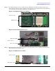
• LEDs. The front panel LEDs and LAN LEDs of the server blade change color and blink to help identify
specific problems, and display LAN activity.
• The SEL provides detailed information about the errors identified by the LEDs.
For system alerts of levels 3-5, the attention condition on the system LED can be cleared by accessing the logs
using the sl command, available in the iLO MP command mode. To access the iLO MP from the console
serial port, enter
Ctrl+B or ESC-(.
If the LEDs and SEL do not give you enough information for you to identify the problem you are experiencing,
HP also provides diagnostic tools with each operating system (see “Troubleshooting Tools” on page 75 for
more details).
NOTE Always check the iLO MP SEL in the case of a blinking yellow or red front panel health LED,
before replacing any hardware.
Recommended Troubleshooting Methodology
The recommended methodology for troubleshooting a server blade error or fault is as follows:
Step 1. Consult the system console for any messages, emails, etc., pertaining to a server blade error or
fault.
Step 2. View the front panel LEDs (power and health), locally; or remotely through the MP vfp command.
Step 3. Compare the state of the server blade’s LEDs (off; flashing or steady; red, green, or amber) with the
LED states listed in Table 5-2 on page 70.
Step 4. Go to the step number of Table 5-3 on page 71, as specified in the rightmost column of Table 5-2 on
page 70, located in the row which corresponds to your front panel LED display state.
Step 5. Read the symptom/condition information in the leftmost column of Table 5-3 on page 71.
Step 6. Perform the action(s) specified in the “Action” column.
Step 7. If more details are required or desired, refer to the appropriate subsection of this chapter, where
this information is provided in the “Action” column. The “Action” you are directed to perform may
be to access and read one or more error logs (the event log and/or the forward progress log).
You can follow the recommended troubleshooting methodology, and use Table 5-3 and Table 5-4 on page 73, or
go directly to the subsection of this chapter which corresponds to your own entry point of choice. Table 5-1
provides the corresponding subsection or location title for these different entry points (for example, to start by
examining the logs, go directly to “Errors and Error Logs” on page 81).
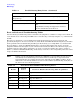
Table 5-1 Troubleshooting Entry Points
Entry Point Subsection or Location
Front panel LEDs Refer to “Basic and Advanced Troubleshooting
Tables” on page 70 and “Troubleshooting Tools” on
page 75.