
User Service Guide, Second Edition - HP Integrity BL60p Server Blade


Troubleshooting
Boot Process LEDs
Chapter 5
92
LAN LEDs
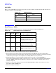
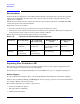
There are four LAN LEDs on the front panel of the server blade. They are NIC 1 through NIC 4. Table 5-14
details the functions of the LAN LEDs.
Boot Process LEDs
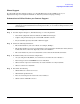
Table 5-15 shows the normal boot process, as reflected in changes to front panel LED states:
The following list itemizes the steps that characterize basic platform boot flow:
1. Server blade power switch requests power from the Management Module (the microcontroller that
manages the enclosure power and cooling). Once the power is request is granted, server blade power turns
on. After the power sequence has completed successfully, BMC releases system reset.
2. Initial CPU firmware code fetch is Platform Abstraction Layer (PAL) code from FEPROM in
processor-dependent hardware (PDH), retrieved 4 bytes at a time by the data multiplexer/demultiplexer
controller (DMDC) in Zx1. No shared memory or I/O devices are available at this time. They are not
initially configured.
3. Firmware code stack is initially in battery-backed RAM (BBRAM) in PDH, retrieved 4 byes at a time,
through the PDH and DMD buses.
4. PAL code configures all CPUs.
Table 5-14 1GB LAN States
LED Color State
Off No link
Steady Green Link found
Flashing Green LAN activity on network link
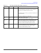
Table 5-15 Normal Boot Process LED States
Step Health Power
Normal Power-Up
Through HP-UX Boot
1 Off Off No AC power to the server blade.
2 Off Amber Server blade is shut down
(server is off), AC power and
standby power is active, last
health status was healthy.
3Off Steady
Green
Server blade power rails are on
when Power switch is toggled.
Hardware drives power LED.
4Steady
green
Steady
green
Server blade has powered up and
is either at EFI, booting, or at
OS.