
User Service Guide, Second Edition - HP Integrity BL60p Server Blade


Introduction
Server Blade Components
Chapter 1
19
Server Blade Components
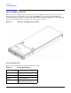
The following sections detail the components of the server blade. They include:
•“SCSI Backplane”
• “I/O Subsystem (Communications Module)”
• “Memory Subsystem”
• “Power Subsystem (on System Board)”
• “CPU / Core Electronics Complex”
SCSI Backplane
The server blade SCSI backplane is a dual disk, single channel, Ultra320 disk subsystem. It is designed
specifically for the BL60p server blade.
The server blade SCSI backplane provides the following key features:
• Drive configuration: Two low-profile disk drives (28.5 mm pitch)
• Drive carrier: Common carrier
• SCSI bus configuration: Single bus
• SCSI specification: Ultra320 (backward compatible with Ultra160)
• SCSI drive interface: Low-voltage differential only
• I2C EEPROM for FRU-ID information
• Hot-swap circuitry
• SCSI bus reset circuitry
• Drive activity LEDs
An LVD SCSI cable connects the SCSI backplane board to the server blade system board. A separate power
cable from the system board provides the power to the disks and other circuitry. The power cable also contains
the I2C bus lines, which provide a data path to the EEPROM.
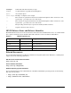
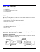
SCSI Backplane Physical Diagram
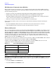
Figure 1-2 shows a physical diagram of the SCSI backplane board for the server blade system. The board
blank outline shown is for illustrative purposes only.
Figure 1-2 SCSI Backplane Physical Diagram
SCSI Termination
ACT
ACT
Activity LEDs,
LED Keepouts
SCSI Bus Connection J1
(backside)
J2 SCSI Connection
ID=0
J3 SCSI Connection
ID=1
J4 Power
Temp Sensor