
User Service Guide, Second Edition - HP Integrity BL60p Server Blade


Introduction
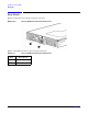
Server Blade Components
Chapter 1
21
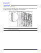
Power Subsystem (on System Board)
The server blade DC-to-DC power subsystem has two major components: the input fuse, and the DC-to-DC
conversion circuit. The input fuse functionality provides an electronic fuse to support insertion and removal of
individual blades while -48V DC inlet power is present on the enclosure backplane. The DC-to-DC conversion
circuit modules take the -48 VDC power from the enclosure backplane through the input fuse, and generates
a non-switched 12 V output rail.
All switched voltage rails in the design are provided through point-of-load (POL) converters that tap into this
12 V nonswitched rail. CPU power pods also connect to this nonswitched 12 V rail, and are controlled through
their respective enable pins. A nonswitched 3.3 V standby voltage rail is always present to support power
management, minimal fans, baseboard management control (BMC), system management, and portions of the
LAN circuitry. The switched POL voltage rails are 3.3 V, 5 V, 2.5 V, 1.8 V, 1.5 V, and 1.25 V.
The DC-to-DC conversion circuit 12 V output is connected to DC power distribution and control logic before
being sent on to the system board for direct use and for feeding a distributed system of DC-to-DC converters
(POLs), which generate the operating voltages that power the system circuitry. The 12 V and 3.3 V standby
power rails are energized whenever -48 VDC power is present to the blade.
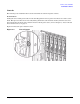
CPU / Core Electronics Complex
The server blade system board houses two Zero Insertion Force (ZIF) CPU sockets, two application-specific
integrated circuits (ASICs), clock generation and distribution circuitry, voltage conversion, boundary scan,
in-target probe for processors (ITP), and debug features.
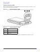
Intel® Itanium 2® Processor Module
The processor in the system is an Intel® Itanium 2® moderate-power (99 W), moderate cost processor. The
processor operates at 1.6 GHz, and has 3 MB of level 2 cache enabled. The processor module includes the
processor chip, the processor power pod (12 VDC in), a custom passive heatsink assembly (unique for the
BL60p server blade), and the hardware to attach all of the module pieces together.
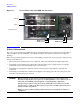
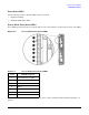
The processors are connected to the main chipset component through the front-side bus (FSB). In the server
blade, the FSB operates at 200 MHz. Since each clock edge transfers data, the data transfer rate is 400
MTransfers/s peak (approximately 6 GB/s). One end of the FSB is electrically terminated with the Zx1 ASIC.
The other end of the bus is terminated with a processor module. In the middle is a slot for an additional
processor. For the system to function properly, mount the processor in the slot farthest away from the ASIC
(the CPU 0 slot) to electrically terminate the FSB. Refer to for the slot locations
Each processor module includes a power pod component that is fed 12 V from the system board through a
pigtail cable. The power pod generates the power rail required by the processor. For signal connections, the
processor module is attached to the system board through a ZIF socket. The processor is also secured by
mechanical attachment to a bolster plate and frame apparatus attached to the system board.