
User Service Guide, Second Edition - HP Integrity BL60p Server Blade

Removing and Replacing Components
Removing and Replacing DIMMs
Chapter 4
56
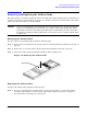
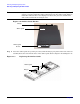
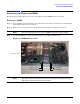
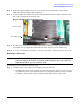
Figure 4-17 Removing a DIMM
Step 4. Open the DIMM slot latches (1). Refer to Figure 4-17.
Step 5. Remove the DIMM from the slot (2).
IMPORTANT Always install DIMMs in identical pairs. DIMMs do not seat fully if turned the wrong way.
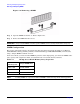
DIMM Configuration
The memory subsystem supports only Double Data Rate Synchronous Dynamic Random Access Memory
(DDR SDRAM) technology utilizing industry-standard PC2100 type DDR SDRAM DIMMs, 1.2-inches tall,
using a 184-pin JEDEC standard connector.
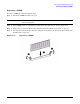
In the server blade, you must load the DIMMs in pairs. To enable chip sparing, you must four DIMMs of the
same capacity and configuration. Table 4-1 summarizes the server blade memory solutions.
NOTE Loading DIMMs as a quad (four identical DIMMs) enables lock-step mode and chip sparing.
Table 4-1 BL60p Server Blade Memory Array Capacities
Min / Max
Memory Size
Single DIMM Sizes
1 GB / 2 GB 512 MB DIMM
2 GB / 4 GB 1 GB DIMM
4 GB / 8 GB 2 GB DIMM