
User Service Guide, Second Edition - HP Integrity BL60p Server Blade

Removing and Replacing Components
Removing and Replacing a Processor
Chapter 4
58
Removing and Replacing a Processor
Use the following procedures to remove and replace a processor in your server blade. Be aware that once the
processor and power pod are assembled, the module is very delicate and you must pick it up from both sides of
the module to avoid damaging the connector.
NOTE The Processor load order is slot CPU 0, then slot CPU 1. The CPU 0 slot is the slot closest to the
edge of the chassis. Refer to Figure 4-19 for CPU slot locations.
Removing a Processor
CAUTION Use care when handling the processor and power pod module when installing and
removing. Support the module on both sides when picking it up, or the connector
might break, and the processor will not work.
To remove a processor, perform the following steps (removing CPU 1 is shown in this procedure):
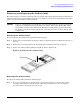
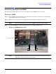
Step 1. Power off the server, and remove it from the enclosure. Refer to “Preparing the Server Blade for
Servicing” on page 44.
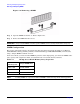
Step 2. Remove the access panel. Refer to “Removing the Server Blade Access Panel” on page 47.
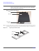
Step 3. Remove the airflow guide. Refer to “Removing the Airflow Guide” on page 51.
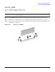
Step 4. Remove the fan assembly. You need to remove the fan assembly to access the processor power
cables. Refer to “Removing the Fan Assembly” on page 53.
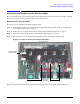
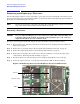
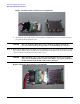
Step 5. Disconnect the power cable from the processor and power pod module you are removing.
Step 6. Loosen the captive screws (1 - 2) on the power pod with the (ACX-15) Torx screwdriver.
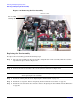
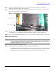
Figure 4-19 Removing the Processor Module on the Server Blade Board
Front of server
6
5
4
2
1
CPU 0
CPU 1
2
3