
User Service Guide, Second Edition - HP Integrity BL60p Server Blade

Removing and Replacing Components
Removing and Replacing a Processor
Chapter 4
59
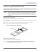
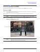
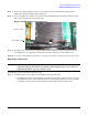
Step 7. Loosen the captive shoulder screws (3 - 6) on the processor heat sink in the order shown in
Figure 4-19 with the (ACX-15) Torx screwdriver.
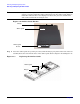
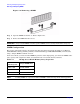
Step 8. Loosen the ZIF socket with the 2.5 mm hex end of the ACX-15 Torx screwdriver. Turn the socket
180º counter clockwise. Refer to Figure 4-20.
Figure 4-20 ZIF Socket on the Processor
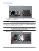
Step 9. Carefully remove the processor and power pod module by lifting it straight up from the system
board. Make sure to support the module from both sides, and place it in an antistatic bag.
Step 10. If you are converting the server blade to a one-processor system, continue with step 8 on page 62.
Replacing a Processor
CAUTION Use care when handling the processor and power pod module when installing and
removing. Support the module on both sides when picking it up, or the connector
might break, and the processor will not work.
To install the processor, perform the following steps:
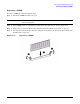
Step 1. Assemble the processor and power pod module by doing the following:
a. Carefully remove the processor and power pod from its packaging. Remove the pin cover and
any additional protective material from the processor and power pod. They are not assembled
for shipment, and you must assemble them before installation. Refer to Figure 4-21.
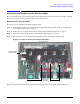
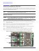
Front of server
CPU 1 ZIF socket