
User Service Guide, Second Edition - HP Integrity BL60p Server Blade


Removing and Replacing Components
Removing and Replacing a Processor
Chapter 4
61
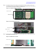
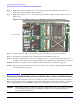
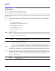
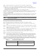
Step 3. Carefully insert the processor module into the empty CPU slot (CPU 1 is shown) on the server
blade system board. Line up the guide pins on the processor to the alignment holes in the CPU slot
to seat the CPU correctly. Refer to Figure 4-23 and Figure 4-24.
Figure 4-23 Alignment Holes in CPU Slot
Figure 4-24 Installing the Processor
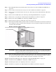
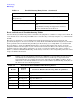
Step 4. Tighten the ZIF socket with the 2.5 mm hex end of the ACX-15 Torx screwdriver. Turn the socket
180º clockwise. Refer to Figure 4-25.
Figure 4-25 ZIF Socket on CPU 1
Front of server
Alignment holes
Front of server
CPU 1 slot (empty)
CPU 0 slot (filled)
Front of server
CPU 1 ZIF socket