
User Service Guide, Second Edition - HP Integrity BL60p Server Blade

Troubleshooting
Enclosure Information
Chapter 5
88
Enclosure Information
This installation document only covers the BL60p server blade itself, and does not include any specific server
blade enclosure information. For server blade enclosure information, go to:
http://h20000.www2.hp.com/bc/docs/support/SupportManual/c00172260/c00172260.pdf
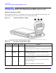
Cooling Subsystem
Each server blade contains 4 dual-rotor cooling fans. Three of the four cooling fans cool both processors and
the communications module. One of the four cooling fans cools the PDH module, the Zx1 chip, and the
memory DIMMs.
Communications Module (LBAs, Ropes, and PDH/PCI-X Buses)
This subsection provides information on troubleshooting issues with the internal PCI-X buses.
I/O Subsystem Behaviors
The main role of the I/O subsystem is to transfer blocks of data and instruction words between physical
shared memory and virtual memory (system disks/disk array). The system boot is the first time blocks of data
and instructions words are transferred into physical shared memory from a local disk/DVD, or from a remote
disk on another server through multiple LAN transfers. This process is referred to as Direct Memory Access
(DMA), and is initiated by I/O devices located in core I/O or on I/O device controllers, and does not involve any
processors.
A secondary role of the I/O subsystem is to transfer four bytes of data between the internal registers within
each CPU core, and the internal control/store registers within the Zx1/PDH /Local Bus Adapters (LBA) and
device controller chips. This process is referred to as programmed I/O, and is initiated by any CPU executing
external LOAD/STORE instructions. (Note that both system firmware and the HP-UX kernel use this method
to initiate DMA transfers.)
Customer Messaging Policy
• Always point the customer to the SEL for any action from low level I/O subsystem faults. IPMI events in
SEL/FPL provide the logical Acpi path of the suspect I/O subsystem FRU. Use Table 5-12 to determine the
physical device controller.