HP Integrity BL860c i2, BL870c i2 & BL890c i2 Server Blade Installation Guide Abstract This document contains specific information that is intended for users of this HP product.
© Copyright 2010, 2013 Hewlett-Packard Development Company, L.P. The information contained herein is subject to change without notice. The only warranties for HP products and services are set forth in the express warranty statements accompanying such products and services. Nothing herein should be construed as constituting an additional warranty. HP shall not be liable for technical or editorial errors or omissions contained herein.
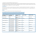
Contents 1 Installing the server blade into the enclosure..................................................4 Installation sequence and checklist..............................................................................................4 Installing and powering on the server blade.................................................................................4 Preparing the enclosure........................................................................................................
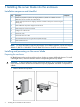
1 Installing the server blade into the enclosure Installation sequence and checklist Step Description 1 Perform site preparation (see the HP Integrity BL860c i2, BL870c i2 & BL890c i2 Server Blade User Service Guide for more information). 2 Unpack and inspect the server shipping container and then inventory the contents using the packing slip. 3 Install additional components shipped with the server. 4 Install and power on the server blade. 5 Configure iLO 3 MP access. 6 Access iLO 3 MP.
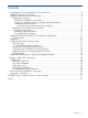
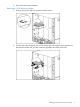
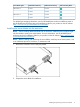
2. Remove the three adjacent blanks. Removing a c7000 device bay divider 1. Slide the device bay shelf locking tab to the left to open it. 2. Push the device bay shelf back until it stops, lift the right side slightly to disengage the two tabs from the divider wall, and then rotate the right edge downward (clockwise).
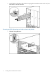
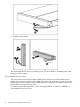
3. Lift the left side of the device bay shelf to disengage the three tabs from the divider wall, and then remove it from the enclosure. Removing a c3000 device bay mini-divider or device bay divider 1. 6 Slide the locking tab down.
2. Remove the mini-divider or divider: • c3000 mini-divider: Push the divider toward the back of the enclosure until the divider drops out of the enclosure. • a. b. c. d. c3000 divider Push the divider toward the back of the enclosure until it stops. Slide the divider to the left to disengage the tabs from the wall. Rotate the divider clockwise. Remove the divider from the enclosure.
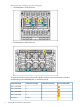
Interconnect bay numbering and device mapping • HP BladeSystem c7000 Enclosure • HP BladeSystem c3000 Enclosure To support network connections for specific signals, install an interconnect module in the bay corresponding to the embedded NIC or mezzanine signals.
Server blade signal c7000 interconnect bay c3000 interconnect bay Mezzanine 2 5 and 6 3 and 4 7 and 8 3 and 4 5 and 6 3 and 4 7 and 8 3 and 4 Mezzanine 3 Interconnect bay labels For detailed port mapping information, see the HP BladeSystem enclosure installation poster or the HP BladeSystem enclosure setup and installation guide for your product on the HP website (http://www.hp.com/go/bladesystem/documentation).
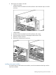
3. Install the server blade. The server blade should come up to standby power. The server blade is at standby power if the blade power LED is amber. Server blade power states The server blade has three power states: standby power, full power, and off. Install the server blade into the enclosure to achieve the standby power state. Server blades are set to power on to standby power when installed in a server blade enclosure. Verify the power state by viewing the LEDs on the front panel, and using Table 1.
Table 1 Power States Power States Server Blade Installed in Enclosure? Front Panel Power Button Activated? Standby Power Applied? DC Power Applied? Standby power Yes No Yes No Full power Yes Yes Yes Yes Off No No No No Powering on the server blade Use one of the following methods to power on the server blade: NOTE: To power on blades in a conjoined configuration, only power on the Monarch blade. • Use a virtual power button selection through iLO 3.
NOTE: Before installing the Blade Link for BL870c i2 or BL890c i2, make sure the following statements are true: • All blades have the same CPU SKUs • All blades have the same hardware revision (only use BL860c i2, BL870c i2, or BL890c i2 Server Blades) • All blades have CPU0 installed • All blades have the same firmware revision set • All blades follow the memory loading rules for your configuration, see the HP Integrity BL860c i2, BL870c i2 & BL890c i2 Server Blade User Service Guide for more info
Class BL4 Number of Blade Link conjoined part number blades Supported enclosures Blade location rules Partner blade support? Partner blade half-height bay number / Server blade full-height bay number AD399-67011 2 (BL870c i2) c3000 only Bays 2&3 with No Monarch blade in even bay using full-height numbering.
12. Log into iLO 3 on the Monarch blade. For more information, see the HP Integrity iLO3 Operations Guide. 13. In iLO 3, go to the Command Menu and execute xd -r to reboot all of the iLO 3s in the conjoined set. 14. Still in the iLO 3 Command Menu, power on the Monarch blade with the PC -on -nc command. Powering on the Monarch blade will power the entire conjoined system on. 15. Boot the Monarch blade. Booting the Monarch blade boots the entire conjoined system.
Using iLO 3, you can: • Remotely power on, power off, or reboot the host server. • Send alerts from iLO 3 regardless of the state of the host server. • Access advanced troubleshooting features through the iLO 3 interface. For more information about iLO 3 basic features, see the iLO 3 documentation on the HP website (http://www.hp.com/servers/lights-out). Accessing UEFI or the OS from iLO 3 MP UEFI is an architecture that provides an interface between the server blade OS and the server blade firmware.
UEFI Front Page If you are at the UEFI shell prompt, enter exit to get to the UEFI Front Page. To view boot options, or launch a specific boot option, press B or b to launch the Boot Manager.
To configure specific devices, press D or d to launch the Device Manager. This is an advanced feature and should only be performed when directed. To perform maintenance on the system such as adding, deleting, or reordering boot options, press M or m to launch the Boot Maintenance Manager. To perform more advanced operations, press S or s to launch the UEFI Shell. To view the iLO 3 LAN configuration, press I or i to launch the iLO 3 Setup Tool.
Operating system is loaded onto the server blade If the OS is loaded on your server blade, normally UEFI will automatically boot to the OS. If the UEFI Front Page is loaded, press ENTER to start auto boot, or B or b to select a specific boot option for your OS. • Use your standard OS logon procedures, or see your OS documentation to log on to your OS. Operating system is not loaded onto the server blade There are two options on how to load the OS if it is not loaded onto your server blade.
2 Support and other resources Contacting HP Before you contact HP Be sure to have the following information available before you call contact HP: • Technical support registration number (if applicable) • Product serial number • Product model name and number • Product identification number • Applicable error message • Add-on boards or hardware • Third-party hardware or software • Operating system type and revision level HP contact information For the name of the nearest HP authorized reseller
HP Insight Remote Support Software HP strongly recommends that you install HP Insight Remote Support software to complete the installation or upgrade of your product and to enable improved delivery of your HP Warranty, HP Care Pack Service or HP contractual support agreement.
CAUTION A caution calls attention to important information that if not understood or followed will result in data loss, data corruption, or damage to hardware or software. IMPORTANT This alert provides essential information to explain a concept or to complete a task NOTE A note contains additional information to emphasize or supplement important points of the main text.
Standard terms, abbreviations, and acronyms A ASIC Application-specific integrated circuit Auxiliary Any blade in a conjoined server other than the lowest-numbered blade B BBRAM Battery-backed RAM BBWC Battery Backed Write Cache BCH Boot console handler C CE Customer engineer CEC Core electronics complex CMC Corrected machine check CPE Corrected platform errors CRU Customer replaceable unit CSR Control status registers D DDNS Dynamic domain name system DHCP Dynamic host configuratio
L LDAP Lightweight directory access protocol LVM Logical volume manager M Monarch Designates a single-blade server, or lowest-numbered blade in a conjoined server MP Management processor MPS Maximum payload size N NIC Network interface card NVRAM Non-Volatile RAM O OA Onboard Administrator ORCA Option Rom Configuration for Arrays P PA-RISC Precision Architecture, Reduced Instruction Set Computing PCA Printed circuit assembly PCI Peripheral component interface PCI-X Peripheral compon
TUI Text user interface U UART Universal asynchronous receiver-transmitter UEFI Unified Extensible Firmware Interface, replaces EFI.
Index B Blade Link installing, 11 C c-Class enclosure see enclosure E enclosure interconnect mapping, 8 interconnect modules, 7 LAN ports, 7 F firmware updates, 18 H HP Smart Update Manager, 18 HP-UX Ignite, 18 HPSUM see HP Smart Update Manager I iLO 3 MP accessing UEFI from, 15 installing Blade Link, 11 server blade into enclosure, 4, 9 N NICs locations on enclosure, 8 NVRAM configuration utility, 17 P power button, 11 powering off, server blade, 11 powering on default, automatically, 10, 11 server