
HP Virtual Connect for c-Class BladeSystem Version 3.00 Setup and Installation Guide for HP Integrity BL8x0c i2 Series Server Blades, Fifth Edition

Installation 60
The network administrator can choose to reduce the number of cables between the Virtual Connect
enclosure and the data center switches by mapping multiple networks to a single, shared uplink port. In
this case, a network is not just mapped to an uplink port, but to a VLAN on that port. This configuration
requires VLAN tags to be added to each packet as it leaves the Virtual Connect domain and that packets
entering the Virtual Connect domain be tagged. The VLAN tag is stripped from packets entering the
Virtual Connect domain before they are routed to the appropriate server.
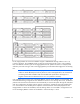
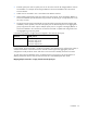
In the following example, an uplink port is defined as a shared uplink port so that it can then be used as
the external connection for multiple networks.
Shared_Uplink_Port_A = Enclosure1:Bay1:PortX2
Network Shared uplink port and VLAN
Production_Network Shared_Uplink_Port_A:VLAN_15
Dev_Network Shared_Uplink_Port_A:VLAN_21
Backup_Network Shared_Uplink_Port_A:VLAN_32
iSCSI_Storage_Network Shared_Uplink_Port_A:VLAN_76
Because appropriate VLAN tags are added as the packets leave the enclosure, this type of uplink should
not be used in cases where VLAN tags are already added on the server itself. The system drops any
Ethernet packets with server-inserted VLAN tags that are received on networks connected to shared uplink
ports.
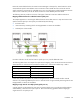
Mapping multiple networks to a shared uplink port set
It is also possible to map multiple VLAN-tagged networks to a set of shared uplink ports. The resulting
shared uplink port set allows for the minimum number of cables while still providing for link aggregation
and failover.
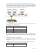
In the following example, a shared uplink port set is first defined to provide aggregation and failover.
Shared_Uplink_Set_A = {Enclosure1:Bay1:PortX2, Enclosure1:Bay2:PortX2}
Network Shared uplink port set and VLAN
Production_Network Shared_Uplink_Set_A:VLAN_15