
HP Virtual Connect for c-Class BladeSystem Version 3.00 Setup and Installation Guide for HP Integrity BL8x0c i2 Series Server Blades, Fifth Edition

Installation 61
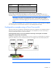
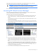
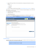
Network Shared uplink port set and VLAN
Dev_Network Shared_Uplink_Set_A:VLAN_21
Backup_Network Shared_Uplink_Set_A:VLAN_32
iSCSI_Storage_Networ
k
Shared_Uplink_Set_A:VLAN_76
In this example, all of the defined networks share a single active uplink port (such as
Enclosure1:Bay1:PortX2) using VLAN tagging, while the second link in the shared uplink port set is
available for failover. The shared uplink port set can also be constructed of multiple 1-Gb external ports.
IMPORTANT: One network can be designated as a native VLAN, causing all untagged
incoming Ethernet packets to be placed on this network. See the additional information on
shared uplink sets and VLAN tagging in the HP Virtual Connect for c-Class BladeSystem User
Guide.
To make Virtual Connect Manager aware of shared network connections, see the information on defining
new shared uplink sets in the HP Virtual Connect for c-Class BladeSystem User Guide.
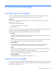
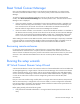
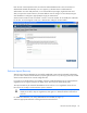
Configuration example using a Cisco Core switch
There are several ways to implement a redundant Virtual Connect configuration. This example provides a
reference for anyone unfamiliar with switch configurations. This example is just one of several ways to
connect an HP Virtual Connect to a Cisco Core switch.
Connecting Virtual Connect to a Cisco Core/distribution switch using a shared uplink set and VLAN
tagging done at the VC/data center boundary
In the following example, LACP is used on the Cisco Switch to connect to a shared uplink set using three
uplink ports. VLANs 10, 20, 30, and 40 from the network are tagged on the three shared uplink ports.
IMPORTANT: Change Channel Mode to LACP on the Cisco switch.