HP BladeSystem c7000 Carrier-Grade Options Installation Guide Part Number 5991-8062 September 2009 (Second Edition)
© Copyright 2009 Hewlett-Packard Development Company, L.P. The information contained herein is subject to change without notice. The only warranties for HP products and services are set forth in the express warranty statements accompanying such products and services. Nothing herein should be construed as constituting an additional warranty. HP shall not be liable for technical or editorial errors or omissions contained herein.
Contents Rack options ................................................................................................................................ 4 HP Seismic Rack........................................................................................................................................ 4 HP Seismic Rack Casters ............................................................................................................................ 4 Shipping carton contents .............................
Rack options HP Seismic Rack Additional documentation for the HP Seismic Rack can be found on the HP website (http://www.hp.com/support/Seismic_Rack_UG_en). HP Seismic Rack Casters The seismic rack casters are designed for short-distance moves over smooth, hard surfaces or short-pile carpeting. Carrier-grade racks do not support the use of an unloading ramp.
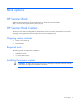
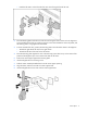
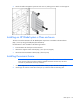
Item Description 1 Caster 2 Caster jack screw 3 Caster support bolts 4 Backing plate 5 Mounting plate To install the seismic casters: 1. Retrieve the appropriate caster (left or right) from the kit. o Install the right casters on the right side of the rack when facing the front of the rack.
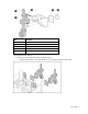
o Install the left casters on the left side of the rack when facing the front of the rack. 2. Place the backing plate inside the rack with the nuts facing the interior of the rack. The alignment pins protrude from the hole you used to access the screws that mounted the rack to the pallet, and the backing plate is snug against the sheet metal. 3.
WARNING: Do not raise the rack more than necessary. Have someone watch as you raise the rack and warn you if there is any excessive motion or tipping. 10. Repeat the installation steps to install the remaining casters. 11. Using a wrench, raise the rack by turning the caster jack screws clockwise, a little at a time, until the rack is high enough to slide the pallet out from under the rack. IMPORTANT: Do not turn the jack screw on one caster more than four turns clockwise.
4. Install the seismic brace ("Installing the seismic brace" on page 10). Shipping carton contents • BLc7000 Seismic Brace • BLc7000 Seismic Rack Mount Kit • BLc7000 Cable Management System • Documentation Required tools The following tools are required for installation: • Torx screwdriver Installing the rack mount bracket NOTE: The U locations are noted in the following procedure for enclosures installed in the lower portion of the rack.
2. Install one cage nut into the top hole of U4 and the middle hole of U9 (U15 and U20) in the front mounting rails. Installing the cable management system NOTE: The U locations are noted in the following procedure for enclosures installed in the lower portion of the rack. When installing multiple enclosures into the rack, use the U locations in parentheses for the top enclosure. 1. Install one cage nut into the bottom holes of U5 or U9 (U16 and U20) in the rear mounting rails.
2. Attach the cable management system to each rear rail, making sure to attach it to the cage nut. Installing an HP BladeSystem c-Class enclosure The most current documentation for HP BladeSystem components is available at the HP website (http://www.hp.com/go/bladesystem/documentation). Documentation is also available in the following locations: • Documentation CD that ships with the enclosure • HP Business Support Center website (http://www.hp.
3. From the front, slide the top brace on top of the enclosure. 4. Secure the rear brace to the top brace using the provided screws. The longer flange of the rear brace must be located on the bottom. 5. From the rear, insert the two rear brackets between the enclosure and the rack. The top tab rests on the top brace. 6. Insert the top front brackets into the slots in the front of the enclosure. 7. Secure the brackets to the top brace, using the provided screws.
Shipping carton contents • HP BladeSystem Cable Management Tray • Mounting rails with attached locking brackets • M5 screws (4) • Documentation Required tools The following tools are required for installation: • Phillips screwdriver • Fasteners or cable ties Installing the cable management tray To install the cable management tray: 1. On each side of the rack, align the center holes in the rack with the two center holes on the rail bracket. o For the lower tray installation, use 12U and 13U.
Routing cables through the cable management tray When routing cables through the cable management tray route the cables from the hub to the back of the cable management tray, and then through to the front of the rack. Securing cables CAUTION: To prevent accidental kinks, snags, or overbending, dress and secure all cables. CAUTION: Do not use cable ties or wire ties on fiber cables. Use hook-and-loop straps to keep spooled cable in place. The enclosure has four cable guides on each side of the switch bays.
2. Install a wire tie for copper wire or a hook-and-loop strap for fiber cable. Ties or fasteners cannot exceed 1.3 cm (0.5 in) wide or 12.7 cm (5.0 in) long. 3. Secure each guide to the cable management system frame.
You can also use hook-and-loop straps to fasten cables to the rack. To secure cables to the cable management tray, attach the cables to the slots on the cable management tray with a hook-and-loop strap. HP BladeSystem Breaker Panel NOTE: The breaker panel contains no serviceable internal parts. To install the breaker panel: 1. Install the sheet metal grommet ("Installing the sheet metal grommet" on page 16). 2. Install the breaker panel brackets ("Installing the breaker panel brackets" on page 16).
Required tools The following tools are required for installation: • Phillips screwdriver • Flathead screwdriver • 1mm wrench • T-25 Torx driver • T-20 Torx driver • 14mm socket wrench Installing the sheet metal grommet The sheet metal grommet protects the cables that run through the opening on the top of the rack. To install the sheet metal grommet: 1. From the rear of the rack, unscrew the two top plate nuts, and then remove the rack top. 2. Discard the plate and nuts. 3.
Installing the breaker panel into the rack 1. Align the rack support brackets on the breaker panel with the rail brackets, and slide the breaker panel into the rack. 2. Secure the breaker panel with the screws provided. Power cable connections for the breaker panel WARNING: Only a certified electrician must connect power to the breaker panel.
7. Install the nuts and washers over the lugs. 8. Install the breaker panel rear cover. Installing breaker panel site input power cables WARNING: A qualified electrician must determine the cabling requirements for the input power of the breaker panel. You must verify that the correct size cables are installed into side A and side B of the breaker panel. WARNING: You must disconnect the input cables from the site power or battery before connecting the breaker panel input cables.
9. Connect the site input power cables to the input busbar studs. a. Connect the -48V/-60V red wire to the top busbar on each Side (A & B). b. Connect the RTN black wires to the bottom busbar on each Side (A & B). c. Use the 14mm socket wrench to reinstall the nuts over the lugs. 10. From the front, pull the breaker panel forward, reattach the front mounting brackets, and then secure the breaker panel to the front cage nuts. 11.
Cable Breaker Panel End Red source -48 DC or Black return Red source -48 DC or Black return Red source -48 DC or Black return Input Module End (90° Lug) (45° Lug) (E-PS3) BP-A3 BP-B1 (E-PS4) (E-PS4) BP-B1 BP-B2 (E-PS5) (E-PS5) BP-B2 BP-B3 (E-PS6) (E-PS6) BP-B3 Use the following DC cable connection configuration table to connect the DC power cables to the breaker panel and to the DC input module. Each of these connections is a pair of wires, one for -48V DC and one for return.
2. Referring to the DC cable connection configuration table, connect a black return cable to the right side of the A1 position with a 90° lug. To connect cables from the breaker panel to the DC input module: 1. Referring to the DC cable connection configuration table, connect the red source cable from the breaker panel to the top portion of the DC input module at a 45° angle with a 45° lug. 2.
Grounding the breaker panel Item Description 1 Breaker Panel 2 Double-hole Lug with Nuts 3 Single-hole Lug and Self-threading Screw 4 Ground Rail To ground the breaker panel: 1. Remove the breaker panel rear cover to expose the grounding studs common to the breaker panel. 2. Remove the nuts from the studs. 3. Install the grounding cable onto the studs, and tighten the nuts over the lug. 4. Route the grounding cable, and connect the single-hole lug of the grounding cable to the ground rail.
5. Reinstall the two breaker screws. 6. Switch the breaker on. Breaker panel safety cover A safety cover is included with the breaker panel. The cover consists of a top cover and a bottom cover. Both covers can be removed with the breaker panel installed. Each cover is secured with three screws. To access the output connections, only remove the bottom cover. To access the input connections, remove both the top and bottom covers.
Enclosure options Additional enclosure options Additional documentation for the following options can be found on the HP website: • HP BladeSystem BL860c Server Blade (http://www.hp.com/support/Integrity_BL860c_Server_Blade_USG_en) • HP BladeSystem BL460c Server Blade (http://www.hp.com/support/BL460c_Server_Blade_UG_en) • HP StorageWorks MSA2324 Carrier-Grade Storage Array (http://www.hp.
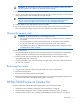
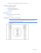
Power supply LEDs Power LED 1 (green) Fault LED 2 (amber) Condition Off Off No power to the power supply On Off Normal Off On Power supply failure Installing a power supply Install the power supplies based on the total number of supplies needed: • Two power supplies: Bays 1 and 4 • Three power supplies: Bays 1, 2, and 4 • Four power supplies: Bays 1, 2, 4, and 5 • Five power supplies: Bays 1, 2, 3, 4, and 5 • Six power supplies: All bays Install power supply blanks in any unused powe
2. Open the power supply bracket. 3. Insert the power supply into the enclosure, and then close the bracket. HP Seismic Rack Mounting Kit for the MSA2324 CG The HP Seismic Rack Mounting Kit for the MSA2324 CG supports installation of the HP StorageWorks MSA2324 Carrier-Grade Storage Array in the HP Seismic Rack.
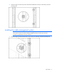
• Washer • Bracket assembly screws (12) Installing the Seismic Rack Mounting Kit 1. Attach the rear brackets to the MSA2324 Carrier-Grade CG 2. Attach the left bracket assembly to the left rack rail. 3. Attach the right bracket assembly to the left right rail. 4. Insert cage nuts into the rack holes. 5. Align the MSA2324 CG with the rails, and then slide it into the rack until the ears of the MSA2324 CG are about 1 to 2 inches from the rack front rails. 6.
7. Attach the single-hole ground cable lug between the front right mounting ear (top hole) and the rack with a lock washer and screw. Item Description 1 Lock washer 2 Screw 3 Flat washer 4 Bolt 5 Ground cable lug. Position between ear and rail (cable not shown) 8. Loosely attach the rear brackets to the rear bracket assemblies. 9. Attach the loose end of the ground cable to the front rack ground rail. 10.
Enclosure options 29
Acronyms and abbreviations CG carrier-grade DC domain controller MSA Modular Smart Array SAS serial attached SCSI Acronyms and abbreviations 30
Index installing the seismic rack mounting kit 27 B breaker breaker breaker breaker breaker breaker breaker breaker panel 15, 16, 17, 18, 19, 22, 23 panel brackets, installing 16 panel, cabling 17, 18, 19 panel, connecting to power supplies 19 panel, grounding 22 panel, installing 16, 17 panel, required tools 16 panel, safety cover 23 C cable management system, installing 9 cable management tray 11, 12, 13 cable management tray, installing 12 cable management tray, required tools 12 cable management tray