HP Integrity BL870c Server Blade Installation Guide HP Part Number: AH232-9007C Published: August 2012 Edition: 4
© Copyright 2008, 2012 Hewlett-Packard Development Company, L. P. Legal Notices The information contained herein is subject to change without notice. The only warranties for HP products and services are set forth in the express warranty statements accompanying such products and services. Nothing herein should be construed as constituting an additional warranty. HP shall not be liable for technical or editorial errors or omissions contained herein. Printed in U.S.A.
Contents About This Document.....................................................................................5 Intended Audience....................................................................................................................5 New and Changed Information in This Edition..............................................................................5 Publishing History.....................................................................................................................
Remote Access Allowed.................................................................................................34 Remote Access Not Allowed ..........................................................................................35 Accessing EFI or the OS From the iLO 2 MP...............................................................................35 EFI Boot Manager..............................................................................................................
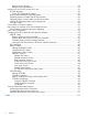
About This Document This document provides information and instructions on servicing the HP Integrity BL870c server blade. The document publication date and part number indicate the document’s current edition. The date changes when a new edition is published. The document part number changes when extensive changes are made. Document updates may be issued between editions to correct errors or document product changes.
Computer output Text displayed by the computer. Ctrl+x A key sequence. A sequence such as Ctrl+x indicates that you must hold down the key labeled Ctrl while you press another key or mouse button. ENVIRONMENT VARIABLE The name of an environment variable, for example, PATH. ERROR NAME The name of an error, usually returned in the errno variable. Key The name of a keyboard key. Return and Enter both refer to the same key. Term The defined use of an important word or phrase.
Windows Operating System Information Find information about administration of the Microsoft Windows operating system at the following website: http://www.microsoft.com/technet/ Diagnostics and Event Monitoring: Hardware Support Tools Complete information about HP hardware support tools, including online and offline diagnostics and event monitoring tools, is on the HP website at: http://www.hp.com/go/hpux-diagnostics-docs Website for HP Technical Support http://welcome.hp.com/country/us/en/contact_us.
For HP technical support: • In the United States, for contact options see the Contact HP United States webpage: (http:// welcome.hp.com/country/us/en/contact_us.html) To contact HP by phone: • ◦ Call 1-800-HP-INVENT (1-800-474-6836). This service is available 24 hours a day, 7 days a week. For continuous quality improvement, calls may be recorded or monitored. ◦ If you have purchased a Care Pack (service upgrade), call 1-800-633-3600.
1 Installing the Server Blade Into the Enclosure This chapter covers the procedures for installing the HP Integrity BL870c server blade into a c7000 enclosure. Safety Information When removing and replacing server components, use care to prevent injury and equipment damage . Many assemblies are sensitive to damage by electrostatic discharge.
Verify Site Preparation Verifying site preparation is an essential factor of a successful server installation, and includes the following tasks: • Gather LAN information. Determine the two IP addresses for the Onboard Administrator integrated Lights Out Management Processor (OA iLO 2) LAN and the server blade iLO 2 MP. • Establish a method to connect to the server console. For more information on console connection methods, see “Accessing the Integrated Lights Out 2 Management Processor” (page 27).
NOTE: If you purchased an additional processor, the IPF Processor Install Toolkit is included with the processor. The server blade has a Torx T-15 screwdriver mounted on the inside of the access panel. Installing a Hot-Plug SAS Disk Drive Use the following procedures if the server blade has a disk drive blank installed and you need to install a hot-plug SAS disk drive. For a list of supported hard disk drives for the server blade, see: http://h18004.www1.hp.com/ products/blades/components/c-class-storage.
2. Close the lever to lock the drive into place (2). Figure 2 Installing a Hot-Plug SAS Disk Drive Installing Internal Components Use these procedures to install internal components that were not factory-installed into the server blade. Before you can install the internal components, you must remove the access panels to install the internal components. Removing the Access Panels There are two access panels on the BL870c server blade. Each panel gives access to different components on the system board.
1. Unlock the cam on the right access panel latch (if necessary) by turning the lock on the access panel latch counterclockwise with a Torx T-15 or flat head screwdriver. See Figure 3. 2. Pull up on the access panel latch (1). This causes the access panel to slide back about 2 cm (0.75 in) (2). 3. Remove the access panel by lifting it straight up and off the server blade (3). Figure 3 Removing the Server Blade Right Access Panel 4.
Figure 4 Removing the Server Blade Left Access Panel After the access panel is off, you can do the following: • Add an additional processor to slot 2 or 3. For more information, see“Installing a Processor” (page 14). • Add additional memory DIMMs. For more information, see “Installing DIMMs” (page 19). Installing a Processor Depending on which processor slot you need to access, you must remove the right access panel or the left access panel.
2. Remove the dust cover from the empty processor slot on the system board (if necessary). a. Remove the processor 1 air baffle (air blocker) on the system board (right side only). Save this piece so you can reinstall it if you return the server blade to a one-processor configuration. Figure 5 (page 15) shows the processor 1 air baffle. Figure 5 Processor 1 air baffle (air blocker). b. Remove the processor 2 and 3 air baffle from the system board by lifting it straight up and out of the server blade.
1 3. Processor 2 air blocker 2 Processor 3 air blocker Make sure the ZIF socket lock for the empty processor slot on the system board is unlocked by turning the cam counterclockwise 180 degrees with the processor installation tool. If the socket lock does not turn, the socket is open and ready for the processor to be installed. Figure 8 shows the ZIF socket lock for processor 1 in the unlocked position.
4. Install the processor into the server by lining up the alignment pins on the processor with the holes in the processor slot. The processor load order is to load the processors into slot 0 and slot 1 on the right side of the system board; then slot 2 and slot 3 on the left side of the system board. For slot locations on the system board, see Figure 9. Figure 9 Processor Slot Identification 5. Ensure the processor is seated by pressing down gently on the processor.
Figure 10 Processor Sequencer 7. Tighten the ZIF socket lock by turning the lock 180 degrees clockwise with the processor installation tool. Press down gently on the processor when tightening the ZIF socket to ensure the lock engages properly. Do not tighten the ZIF socket lock more than 180 degrees in either direction. This severely damages the socket and processor, and renders the system board unusable. 8. 9.
Figure 11 Installing a Processor on the System Board 10. Connect the power cable to the processor power connector. If you are installing processors into the server blade and you are not installing memory DIMMs or mezzanine cards, see “Replacing the Right Access Panel” (page 23). If you are installing DIMMs, see “Installing DIMMs” (page 19). If you are installing mezzanine cards, see “Installing Mezzanine Cards” (page 20).
To install additional memory DIMMs into the server blade: 1. Remove the left access panel from the server blade. See “Removing the Server Blade Left Access Panel” (page 13). 2. Locate the DIMM slots on the memory mezzanine board. See Figure 12. NOTE: 0D. The server blade ships with at least four DIMMs installed in slots 0A, 0B, 0C, and Figure 12 DIMM Slot Locations 3. Ensure the DIMM slot latches are open. CAUTION: Use only HP low profile (1.2 in.) DIMMs.
Figure 13 Mezzanine Port Locations on the System Board 1 2 3 The 1. 2. 3. Mezzanine port 1: PCIe x4 port Mezzanine port 2: PCIe x8 port Mezzanine port 3: PCIe x8 port install order for the mezzanine ports is: PCIe x4 card – Install into slot 1 PCIe x8 card – Install into slot 2 PCIe x8 card – Install into slot 3 If you are only installing PCIe x8 cards, start from mezzanine slot 2, not slot 1. Mezzanine port 1 is lower than mezzanine ports 2 and 3 to enable the cards to be stacked on top of each other.
Figure 14 Mezzanine Port Heights 1 Mezzanine port 1: PCIe x4 port 2 Mezzanine port 2: PCIe x8 port 3 Mezzanine port 3: PCIe x8 port Installing a Mezzanine Card to Port 1 To insert a mezzanine card to the PCIe x4 port 1 on the system board: 1. Line up the plastic pins on the mezzanine card connector with the PCIe x4 port on the system board. 2. Push down on the card directly above the port to seat the card into the port.
3. Tighten the thumbscrews on the mezzanine card circled in Figure 15 (page 23) until snug to secure the card to the system board. Figure 15 Installing Mezzanine Card 1 on the System Board Installing a Mezzanine Card to Ports 2 and 3 To insert a mezzanine card to the PCIe x8 ports 2 and 3 on the system board: 1. Line up the plastic pins on the mezzanine card connector on the PCIe x8 port 2 on the system board. 2. Push down on the card directly above the port to seat the card into port 2. 3.
Figure 16 Replacing the Right Access Panel 4. Lock the access panel cam (if necessary) by turning the cam clockwise with the Torx T–15 or flat head screwdriver. Replacing the Left Access Panel To replace the left access panel: 1. Make sure the left access panel latch is in the open position (sticking up). See Figure 17 (page 25). 2. 3. 24 Place the access panel onto the server blade by lining up the posts on each side of the access panel with the keyways on the server blade chassis (1).
Figure 17 Replacing the Left Access Panel 4. Lock the access panel cam (if necessary) by turning the cam clockwise with the Torx T–15 or flat head screwdriver. Installing and Powering On the Server Blade This section explains how to install the HP Integrity BL870c server blade into a standard c–Class enclosure and power it on. When you install the server blade into the enclosure, by default, the server blade powers up to standby mode. Installing the Server Blade Into the Enclosure The 1. 2. 3. 4.
5. Close the extraction lever (2). The server blade should come up to standby power. The server blade is at standby power if the power button LED and server health LED is amber. IMPORTANT: If the server health LED turns green, and the fan noise increases, the server blade is powering up to full power automatically. Skip the rest of this procedure, and proceed to “Accessing the Integrated Lights Out 2 Management Processor” (page 27).
Powering On the Server Blade Use the following procedure to power on the server blade after it is installed in the enclosure. 1. Ensure the server blade is in standby mode by verifying the power button LED is amber. If the power button LED is green, the server blade has full power. 2. Press the power button momentarily to power on the server blade.
Figure 19 Main Menu of the Front Display Panel 3. Press OK. The View Blade and Port Info screen displays on the front display panel. See Figure 20. Figure 20 The View Blade and Port Info Screen 4. 5. Using the left/right arrows, highlight Blade Info on the bottom of the front display panel. Follow the onscreen directions to select the appropriate server blade, and press OK. The View Blade Info screen displays. See Figure 21.
Figure 21 The View Blade Info Screen 6. 7. 8. 9. Write down the iLO 2 MP IP address that displays on the View Blade info screen. Access the iLO 2 MP through telnet, SSH, or through the web using the assigned DHCP IP address. This ends the “Accessing the iLO 2 MP with DHCP Enabled” procedure. Continue to “Configuring the iLO 2 MP” (page 31). Accessing the iLO 2 MP with No Network Connection Use the following procedure to configure the RS-232 port to enable iLO 2 MP access.
Figure 22 Connecting the SUV Cable to the Server Blade Connecting a Terminal to the Server Blade Use the following procedure to establish a connection from your server to your terminal (or emulator device). CAUTION: Disconnect the SUV cable from the port when not in use. The port and connector are not intended to provide a permanent connection. 1. 2. Connect the standard DB9f to DB9f modem eliminator cable to the RS-232 port on the SUV cable.
Configuring the iLO 2 MP This section includes important security considerations when configuring your server blade for remote access.
iLO 2 MP Security Requirements Depending on how you set up your server blade, there are security concerns regarding whether you allow remote access to the server blade. It is highly recommended that you allow remote access to the server blade. Remote access allows for remote system event log analysis, troubleshooting, and general system administration. During the login process, a warning message displays. If you log in through a terminal (serial or telnet), an ASCII message scrolls by.
To power on the server blade to full power when the server blade is inserted in the enclosure: 1. From the MP Main Menu, enter pr to access the Power Restore Configuration menu. 2. Enter on to set the power restore configuration to power on to full power, as shown below: 3. 4. Enter y to confirm changing the power restore configuration setting. Power on the server through the iLO 2 MP by accessing the Power Control menu. Access the Power Control menu by entering pc from the MP Main Menu. 5.
Remote Access Allowed NOTE: If your server blade has a DHCP server connected to the OA/iLO 2 port on the rear of the enclosure, this procedure is not required. Proceed to “Accessing EFI or the OS From the iLO 2 MP” (page 35). To allow remote access, you should have changed your iLO 2 MP password to secure your server blade. If you have a DHCP server connected to the OA/iLO 2 port on the rear of the enclosure, your access is set.
Remote Access Not Allowed You can disable remote access to the server blade. CAUTION: Use this procedure only if you are disabling remote access to the server blade. Do not disable remote access if you have a DHCP server connected to the OA/iLO 2 port on the rear of the enclosure. This procedure disables all remote access to the server blade and you will lose your ability to access the server blade remotely. To disable DHCP and other remote connections on your server blade: 1.
• From the MP Main Menu, enter co to access the Console Menu. Depending on how the server blade was configured from the factory, and if the OS is installed at the time of purchase, you should be in one of two places: • EFI Boot Manager menu • OS login prompt If the server blade has a factory-installed OS, you can interrupt the boot process to configure your specific EFI parameters. • If you are at the EFI Shell prompt, see “EFI Boot Manager” (page 36).
Server Blade to Enclosure Interface This section shows the location of the RJ-45 LAN ports on the back of the server blade enclosure, and how they correspond with the Network Interface Controller (NIC) LEDs on the front of the server blade. Port Locations on the Rear of the Server Blade Enclosure LAN port mapping depends on the type of I/O card that is installed into the server blade. Figure 24 shows some of the modules available for the c7000 enclosure.
Table 5 Server Blade to Enclosure Interconnect Mapping (continued) Server Blade to c7000 Enclosure Mapping Mezzanine Slot 2 Slots 5 and 6 Mezzanine Slot 3 Slots 7 and 8 NOTE: Dual-width interconnect modules cannot be used in slots 1 or 2. LAN / NIC Configuration Table 6 shows how the EFI and HP-UX LAN ports and front panel NIC numbers match up on the server blade enclosure.
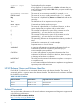
3. To determine the current version of the firmware: a. At the EFI Shell, enter mptutil from the directory that contains mptutil.efi. The following example indicates that the EFI Serial Attached SCSI card utility version is 1.01.12.00: fs0:\EFI\HP\TOOLS\NETWORK> mptutil MPTUTIL-1.01.12.00 Vendor Device Choice ID ID Bus Device ------ ------ ------ --- -----0 1000h 0054h 14h 01h LSI Logic SAS1068 Host Adapter 1 - Refresh b. 4. 5. Press Enter. To update the firmware, use the mptutil command.
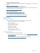
Answer The firmware you flashed on the HBA does not run until a diagnostic reset occurs. If you exit the utility and reenter it, the version string is updated. Question This image does not contain valid nvdata information when I try to flash the firmware. Why? Answer You are expected to concatenate a proper nvdata image to the firmware. MPTUTIL prevents you from flashing an image without a concatenated nvdata image. To concatenate nvdata and firmware, run the mptutil -o -d 64it__l.fw,sas106x.
Home/End Select up, down, left, or right to position the cursor. +/- Use to change items with values in [ ] brackets. Numeric keypad + and numeric keypad - (minus) update a modifiable field to its next relative value. Esc Use to abort the current context operation or exit the current screen. User confirmation is solicited as required if changes were made by user. If you are using a serial console, pressing Esc causes a delay of several seconds before it takes effect.
PCI Dev Indicates the PCI Device assigned by the system BIOS to an adapter (range 0x00 - 0x1F, 0 - 31 decimal) PCI Fnc Indicates the PCI Function assigned by the system BIOS to an adapter (range 0x00 - 0x7, 0 - 7 decimal) FW Revision Displays the Fusion MPT firmware version and type (IR or IT) Status Indicates whether the adapter is or is not eligible for software control (Enabled, Disabled, or Error) Enabled Indicates the EFI Driver is controlling the adapter or will attempt to control the adapter u
where: x.xx.xx.xx refers to the FW version yy refers to the type. The currently supported type is IR.l). SAS Address Displays the SAS Address assigned to this adapter. FW Revision Displays the Fusion MPT firmware version and type (IR or IT). Status Indicates whether an adapter is eligible for configuration utility software control or is reserved for control by other software (Enabled, Disabled, or Error).
Select New Array Type Screen The Select New Array Type screen enables you to view an existing array or create an Integrated Mirror array of two disks, plus an optional hot spare. • To go to the Create New Array screen, select Create IM Volume. • To go to the View Array screen, select View an Existing Array. Create New Array Screen The Create New Array screen enables you to create an array.
Missing Disk is not responding. Failed Disk has failed. Initializing Disk is initializing. CfgOffln Disk is offline at host's request. User Fail Disk is marked failed at host's request. Offline Disk is offline for some other reason. Inactive Disk has been set to inactive. Not Syncd Data on disk is not synchronized with the rest of the array. Primary Disk is the primary disk for a 2 disk mirror and is OK. Secondary Disk is the secondary disk for a 2 disk mirror and is OK.
Status Displays the array status. Bay Displays the device bay location. Device Identifier Displays the device identifier. RAID Disk Specifies the devices (disks) that make up an IM array. If RAID Disk is Yes, the device is part of an IM array, if No, the device is not part of an IM array. This field is grayed out under the following conditions: Hot Spr • The device does not meet the minimum requirements for use in an IM array. • The device is not large enough to mirror data on the primary drive.
No SMART Disk doesn't support SMART and cannot be used in a RAID array. Wrg Intfc Device interface (SAS) differs from existing IM disks. Pred Fail Indicates whether device SMART is predicting device failure (Yes, No). Size(MB) Indicates the size of the device in megabytes (megabyte = 1024 x 1024 = 1,048,576 bytes). If the device is part of a two-disk array, this field reflects the size of the array, not the size of the disks.
Type Displays the RAID type. Scan Order Displays the scan order of the array. Size (MB) Displays the size of this array. Status Displays the status of this array. Exit the SAS Configuration Utility Screen Because some changes only take effect when you exit the utility, exit the utility properly by following these steps: 1. To return to the Adapter List from Adapter Properties, press ESC. 2. To exit the utility from the Adapter List, press ESC.
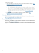
Use the following conventions in command descriptions: • Text in italics must be entered exactly as shown on the command line. • Text surrounded by <> must be replaced with a required parameter. • Text surrounded by [ ] can be replaced by an optional parameter. • Parameters surrounded by {} must be entered one or more times, as appropriate for the command issued. • Command line definition characters (<>, [ ], and {}) cannot be entered on the command line.
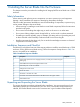
The disk identified by the first SCSI ID on the command line is assigned as the primary disk when creating an IM volume. If the SAS controller is allowed to resynchronize the disks, the data on the primary disk is available by accessing the newly created volume. Using the AUTO Command The AUTO command automatically creates an IM volume on the SAS controllers. The volume is created with the maximum number of disks available for use in the specified volume type.
To ensure that you have the latest version of firmware running on your server, verify the firmware installed on your server blade. If your firmware isn't the latest version, download the it from the web and create a CD to install the firmware on the server. To install the firmware onto your server blade, you must have an external USB DVD drive attached to the server blade. To install an external DVD drive to your server blade, see “Operating System is Not Loaded onto the Server Blade” (page 36) .
Index A access panel removing the left , 13 removing the right , 12 accessing iLO 2 MP, 27 adapter properties screen, 42 antistatic wrist strap, 9 array screen create, 44 manage, 47 view, 45 C cfggen utility, 48 AUTO command, 50 CREATE command, 49 HOTSPARE command, 50 checking the inventory, 10 chip sparing, 19 confirming the packing slip, 10 create array screen, 44 D damaged equipment, 10 DIMMs chip sparing, 19 installation order, 19 installing, 19 slot locations, 20 drvcfg utility, 40 E EFI accessing f
powering on default, automatically, 27 server blade, 27 setting automatic power-on, 33 processor installing, 14 publishing history, 5 V view array screen, 45 VPD information for EFI and RISC firmware, 40 R RAID properties screen, 43 remote access allowing, 34 configuring, 33 disabling, 34, 35 securing, 32 removing hard drive blank, 11 left access panel, 13 right access panel, 12 replacing left access panel, 24 right access panel, 23 returning a damaged server blade, 10 right access panel replacing, 23 RIS