HP Integrity BL870c Server Blade User Service Guide HP Part Number: AH232-9008C Published: August 2012 Edition: 8
© Copyright 2008, 2012 Hewlett-Packard Development Company, L. P. Legal Notices The information contained herein is subject to change without notice. The only warranties for HP products and services are set forth in the express warranty statements accompanying such products and services. Nothing herein should be construed as constituting an additional warranty. HP shall not be liable for technical or editorial errors or omissions contained herein. Printed in U.S.A.
Contents About This Document...................................................................................10 Intended Audience..................................................................................................................10 New and Changed Information in This Edition............................................................................10 Publishing History...................................................................................................................
Installing DIMMs...........................................................................................................36 Installing Mezzanine Cards............................................................................................37 Installing a Mezzanine Card to Port 1.........................................................................39 Installing a Mezzanine Card to Ports 2 and 3..............................................................40 Replacing the Right Access Panel...........
CFGGEN Utility.................................................................................................................65 Starting CFGGEN.........................................................................................................65 CFGGEN Operation.....................................................................................................65 Rules for creating IM volumes and hot spare disks.............................................................66 CFGGEN Commands...........
Basic and Advanced Troubleshooting Tables.........................................................................90 Troubleshooting Tools..............................................................................................................94 Front Panel LEDs................................................................................................................94 Locator LED..................................................................................................................
Removing and Replacing a Hot-Plug SAS Disk Drive..................................................................111 Removing a SAS Disk Drive...............................................................................................111 Replacing a SAS Disk Drive...............................................................................................112 Removing and Replacing Disk Drive Blanks.........................................................................112 Removing a Disk Drive Blank.
Extensible Firmware Interface.................................................................................................146 EFI Commands................................................................................................................147 EFI/POSSE Commands..........................................................................................................149 help..........................................................................................................................
EFI Shell Paths.................................................................................................................169 Boot from a File..........................................................................................................169 Add a Boot Option.....................................................................................................170 Delete Boot Option(s)..................................................................................................
About This Document This document provides information and instructions on servicing the HP Integrity BL870c server blade. The document publication date and part number indicate the document’s current edition. The date changes when a new edition is published. The document part number changes when extensive changes are made. Document updates may be issued between editions to correct errors or document product changes.
Chapter 1 Overview Use this chapter to learn about the features and specifications of the HP Integrity BL870c server blade. Chapter 2 General Site Preparation Guidelines Use this chapter to learn about the necessary steps needed to properly install your server blade in a data center. This includes environmental and facility characteristics. Chapter 3 Installing the Server Blade Use this chapter to learn about installing the server blade into the enclosure.
CAUTION A caution calls attention to important information that if not understood or followed will result in data loss, data corruption, or damage to hardware or software. IMPORTANT This alert provides essential information to explain a concept or to complete a task NOTE A note contains additional information to emphasize or supplement important points of the main text. HP-UX Release Name and Release Identifier Each HP-UX 11i release has an associated release name and release identifier.
• Applicable error message • Add-on boards or hardware • Third-party hardware or software • Operating system type and revision level HP Contact Information For the name of the nearest HP authorized reseller: • In the United States, see the HP US service locator webpage (http://welcome.hp.com/country/ us/en/wwcontact.html.) • In other locations, see the Contact HP worldwide (in English) webpage: http://welcome.hp.com/country/us/en/wwcontact.html.
1 Overview The HP Integrity BL870c server blade is a dense, low-cost, c-Class enclosure-based Intel Itanium Dual-Core processor server blade. The BL870c server blade is a full-height, double-width server blade that holds up to four processors and includes 24 DIMM slots. The BL870c server blade supports the HP-UX, HP OpenVMS, Linux, and Windows operating systems. The BL870c server blade is designed for commercial server blade customers deploying c-Class blade enclosures.
Figure 1 Right View of the Server Blade (access cover removed) 1 2 3 4 5 Mezzanine card 1 port Mezzanine card 2 port Mezzanine card 3 port TPM module (under the processor 0 power cable, if installed) Processor 0 6 7 8 9 10 Processor 1 Front panel SAS disk drives SAS backplane System board Figure 2 (page 15) shows the locations of these components under the left access panel of the BL870c server blade.
SAS Disk Drives There are four SAS disk drive slots on the BL870c server blade. The SAS disk drives have identical LEDs that show the drive status and activity. Figure 3 shows the slot numbers of the SAS hard disk drives. Figure 3 SAS Disk Drive Slots 1 2 SAS disk drive slot 1 SAS disk drive slot 2 3 SAS disk drive slot 3 4 SAS disk drive slot 4 SAS Backplane The SAS disk backplane supports four small form factor (SFF) 2.5 inch hard drives.
The SAS backplane architecture also includes a SAS cable to connect the SAS backplane to the system board, and a USB port on the SAS backplane. The USB port is available to use as: • HP Ignite-UX boot-strap • Hosting a flash boot image • Multifactor authentication device for added security • Typical USB storage medium (for drivers, licenses, etc.) NOTE: The specific USB port usage depends on the operating system and application support.
Memory Subsystem The HP Integrity BL870c server blade supports 24 DIMMs, which are mounted on a removable memory mezzanine board. The server blade physical memory subsystem includes DDR2 SDRAM DIMMs, as well as zx2 scalable memory expanders, memory bus traces, and required termination. The memory subsystem supports only DDR2 SDRAM technology using industry-standard DIMMs. The DIMMs use a 184-pin JEDEC standard connector. The server blade memory subsystem provides two memory cells.
FIRMWARE INFORMATION *System Firmware A Revision: 3.02 [4819] System Firmware B Revision: 3.02 [4819] BMC Revision: 5.20 Management Processor Revision: T.02.
board. Heatsinks, processor metal frames, and bolster plates are part of the mechanical attachment requirements for the processors and the zx2. Enclosure Information This document covers only the BL870c server blade, and does not include specific server blade enclosure information. For server blade enclosure information, see the HP website at: http://h71028.www7.hp.com/enterprise/cache/316735-0-0-0-121.html.
1 2 Front panel LEDs Power button 3 4 Blade extraction handle release button Blade extraction handle 5 Server blade information label CAUTION: Disconnect the local I/O cable from the I/O port when not in use. The connector is not designed to provide a permanent connection. Front Panel LEDs and Controls The server blade contains seven LEDs on the front panel that indicate the server status. The front panel also contains the power button, the SUV port, and pinhole controls.
Figure 6 SAS Disk Drive LEDs 1 Activity LED 2 Status LED For troubleshooting information regarding the SAS disk drive LEDs, see “SAS Disk Drive LEDs” (page 96). SUV Cable and Ports The HP Integrity BL870c server blade has an SUV cable port that accepts the SUV cable. Use the SUV cable to connect the server to external devices, such as a terminal emulator, an external DVD drive, or a monitor. The SUV cable attaches to the front of the server blade in the SUV cable port. Figure 7 shows the SUV cable.
Figure 7 SUV Cable Ports 1 Serial port 2 USB ports (2) 3 Video port NOTE: There is also an internal USB port on the SAS backplane under the right access panel. For the internal USB port location, see “Removing the SAS Backplane” (page 129). Rear Panel See Figure 8 to identify the server blade rear panel connectors.
Figure 8 BL870c Server Blade Rear Panel Connectors 1 24 Power connectors Overview
2 General Site Preparation Guidelines Site preparation guidelines for the HP Integrity BL870c server blade are covered by the c-Class enclosure the server blade mounts in. The server blade also does not have cooling or power systems as part of the server blade. Cooling and power is provided by the c-Class enclosure. Therefore, the server blade power, cooling, and site specifications are included in the c-Class enclosure documentation.
3 Installing the Server Blade Into the Enclosure This chapter covers the procedures for installing the HP Integrity BL870c server blade into a c7000 enclosure. Safety Information When removing and replacing server components, use care to prevent injury and equipment damage . Many assemblies are sensitive to damage by electrostatic discharge.
Verify Site Preparation Verifying site preparation is an essential factor of a successful server installation, and includes the following tasks: • Gather LAN information. Determine the two IP addresses for the Onboard Administrator integrated Lights Out Management Processor (OA iLO 2) LAN and the server blade iLO 2 MP. • Establish a method to connect to the server console. For more information on console connection methods, see “Accessing the Integrated Lights Out 2 Management Processor” (page 44).
NOTE: If you purchased an additional processor, the IPF Processor Install Toolkit is included with the processor. The server blade has a Torx T-15 screwdriver mounted on the inside of the access panel. Installing a Hot-Plug SAS Disk Drive Use the following procedures if the server blade has a disk drive blank installed and you need to install a hot-plug SAS disk drive. For a list of supported hard disk drives for the server blade, see: http://h18004.www1.hp.com/ products/blades/components/c-class-storage.
2. Close the lever to lock the drive into place (2). Figure 10 Installing a Hot-Plug SAS Disk Drive Installing Internal Components Use these procedures to install internal components that were not factory-installed into the server blade. Before you can install the internal components, you must remove the access panels to install the internal components. Removing the Access Panels There are two access panels on the BL870c server blade. Each panel gives access to different components on the system board.
1. Unlock the cam on the right access panel latch (if necessary) by turning the lock on the access panel latch counterclockwise with a Torx T-15 or flat head screwdriver. See Figure 11. 2. Pull up on the access panel latch (1). This causes the access panel to slide back about 2 cm (0.75 in) (2). 3. Remove the access panel by lifting it straight up and off the server blade (3). Figure 11 Removing the Server Blade Right Access Panel 4.
Figure 12 Removing the Server Blade Left Access Panel After the access panel is off, you can do the following: • Add an additional processor to slot 2 or 3. For more information, see“Installing a Processor” (page 31). • Add additional memory DIMMs. For more information, see “Installing DIMMs” (page 36). Installing a Processor Depending on which processor slot you need to access, you must remove the right access panel or the left access panel.
2. Remove the dust cover from the empty processor slot on the system board (if necessary). a. Remove the processor 1 air baffle (air blocker) on the system board (right side only). Save this piece so you can reinstall it if you return the server blade to a one-processor configuration. Figure 13 (page 32) shows the processor 1 air baffle. Figure 13 Processor 1 air baffle (air blocker). b. Remove the processor 2 and 3 air baffle from the system board by lifting it straight up and out of the server blade.
1 3. Processor 2 air blocker 2 Processor 3 air blocker Make sure the ZIF socket lock for the empty processor slot on the system board is unlocked by turning the cam counterclockwise 180 degrees with the processor installation tool. If the socket lock does not turn, the socket is open and ready for the processor to be installed. Figure 16 shows the ZIF socket lock for processor 1 in the unlocked position.
4. Install the processor into the server by lining up the alignment pins on the processor with the holes in the processor slot. The processor load order is to load the processors into slot 0 and slot 1 on the right side of the system board; then slot 2 and slot 3 on the left side of the system board. For slot locations on the system board, see Figure 17. Figure 17 Processor Slot Identification 5. Ensure the processor is seated by pressing down gently on the processor.
Figure 18 Processor Sequencer 7. Tighten the ZIF socket lock by turning the lock 180 degrees clockwise with the processor installation tool. Press down gently on the processor when tightening the ZIF socket to ensure the lock engages properly. Do not tighten the ZIF socket lock more than 180 degrees in either direction. This severely damages the socket and processor, and renders the system board unusable. 8. 9.
Figure 19 Installing a Processor on the System Board 10. Connect the power cable to the processor power connector. If you are installing processors into the server blade and you are not installing memory DIMMs or mezzanine cards, see “Replacing the Right Access Panel” (page 40). If you are installing DIMMs, see “Installing DIMMs” (page 36). If you are installing mezzanine cards, see “Installing Mezzanine Cards” (page 37).
To install additional memory DIMMs into the server blade: 1. Remove the left access panel from the server blade. See “Removing the Server Blade Left Access Panel” (page 30). 2. Locate the DIMM slots on the memory mezzanine board. See Figure 20. NOTE: 0D. The server blade ships with at least four DIMMs installed in slots 0A, 0B, 0C, and Figure 20 DIMM Slot Locations 3. Ensure the DIMM slot latches are open. CAUTION: Use only HP low profile (1.2 in.) DIMMs.
Figure 21 Mezzanine Port Locations on the System Board 1 2 3 The 1. 2. 3. Mezzanine port 1: PCIe x4 port Mezzanine port 2: PCIe x8 port Mezzanine port 3: PCIe x8 port install order for the mezzanine ports is: PCIe x4 card – Install into slot 1 PCIe x8 card – Install into slot 2 PCIe x8 card – Install into slot 3 If you are only installing PCIe x8 cards, start from mezzanine slot 2, not slot 1. Mezzanine port 1 is lower than mezzanine ports 2 and 3 to enable the cards to be stacked on top of each other.
Figure 22 Mezzanine Port Heights 1 Mezzanine port 1: PCIe x4 port 2 Mezzanine port 2: PCIe x8 port 3 Mezzanine port 3: PCIe x8 port Installing a Mezzanine Card to Port 1 To insert a mezzanine card to the PCIe x4 port 1 on the system board: 1. Line up the plastic pins on the mezzanine card connector with the PCIe x4 port on the system board. 2. Push down on the card directly above the port to seat the card into the port.
3. Tighten the thumbscrews on the mezzanine card circled in Figure 23 (page 40) until snug to secure the card to the system board. Figure 23 Installing Mezzanine Card 1 on the System Board Installing a Mezzanine Card to Ports 2 and 3 To insert a mezzanine card to the PCIe x8 ports 2 and 3 on the system board: 1. Line up the plastic pins on the mezzanine card connector on the PCIe x8 port 2 on the system board. 2. Push down on the card directly above the port to seat the card into port 2. 3.
Figure 24 Replacing the Right Access Panel 4. Lock the access panel cam (if necessary) by turning the cam clockwise with the Torx T–15 or flat head screwdriver. Replacing the Left Access Panel To replace the left access panel: 1. Make sure the left access panel latch is in the open position (sticking up). See Figure 25 (page 42). 2. 3. Place the access panel onto the server blade by lining up the posts on each side of the access panel with the keyways on the server blade chassis (1).
Figure 25 Replacing the Left Access Panel 4. Lock the access panel cam (if necessary) by turning the cam clockwise with the Torx T–15 or flat head screwdriver. Installing and Powering On the Server Blade This section explains how to install the HP Integrity BL870c server blade into a standard c–Class enclosure and power it on. When you install the server blade into the enclosure, by default, the server blade powers up to standby mode. Installing the Server Blade Into the Enclosure The 1. 2. 3. 4.
5. Close the extraction lever (2). The server blade should come up to standby power. The server blade is at standby power if the power button LED and server health LED is amber. IMPORTANT: If the server health LED turns green, and the fan noise increases, the server blade is powering up to full power automatically. Skip the rest of this procedure, and proceed to “Accessing the Integrated Lights Out 2 Management Processor” (page 44).
Powering On the Server Blade Use the following procedure to power on the server blade after it is installed in the enclosure. 1. Ensure the server blade is in standby mode by verifying the power button LED is amber. If the power button LED is green, the server blade has full power. 2. Press the power button momentarily to power on the server blade.
Figure 27 Main Menu of the Front Display Panel 3. Press OK. The View Blade and Port Info screen displays on the front display panel. See Figure 28. Figure 28 The View Blade and Port Info Screen 4. 5. Using the left/right arrows, highlight Blade Info on the bottom of the front display panel. Follow the onscreen directions to select the appropriate server blade, and press OK. The View Blade Info screen displays. See Figure 29.
Figure 29 The View Blade Info Screen 6. 7. 8. 9. Write down the iLO 2 MP IP address that displays on the View Blade info screen. Access the iLO 2 MP through telnet, SSH, or through the web using the assigned DHCP IP address. This ends the “Accessing the iLO 2 MP with DHCP Enabled” procedure. Continue to “Configuring the iLO 2 MP” (page 48). Accessing the iLO 2 MP with No Network Connection Use the following procedure to configure the RS-232 port to enable iLO 2 MP access.
Figure 30 Connecting the SUV Cable to the Server Blade Connecting a Terminal to the Server Blade Use the following procedure to establish a connection from your server to your terminal (or emulator device). CAUTION: Disconnect the SUV cable from the port when not in use. The port and connector are not intended to provide a permanent connection. 1. 2. Connect the standard DB9f to DB9f modem eliminator cable to the RS-232 port on the SUV cable.
Configuring the iLO 2 MP This section includes important security considerations when configuring your server blade for remote access.
iLO 2 MP Security Requirements Depending on how you set up your server blade, there are security concerns regarding whether you allow remote access to the server blade. It is highly recommended that you allow remote access to the server blade. Remote access allows for remote system event log analysis, troubleshooting, and general system administration. During the login process, a warning message displays. If you log in through a terminal (serial or telnet), an ASCII message scrolls by.
To power on the server blade to full power when the server blade is inserted in the enclosure: 1. From the MP Main Menu, enter pr to access the Power Restore Configuration menu. 2. Enter on to set the power restore configuration to power on to full power, as shown below: 3. 4. Enter y to confirm changing the power restore configuration setting. Power on the server through the iLO 2 MP by accessing the Power Control menu. Access the Power Control menu by entering pc from the MP Main Menu. 5.
Remote Access Allowed NOTE: If your server blade has a DHCP server connected to the OA/iLO 2 port on the rear of the enclosure, this procedure is not required. Proceed to “Accessing EFI or the OS From the iLO 2 MP” (page 52). To allow remote access, you should have changed your iLO 2 MP password to secure your server blade. If you have a DHCP server connected to the OA/iLO 2 port on the rear of the enclosure, your access is set.
Remote Access Not Allowed You can disable remote access to the server blade. CAUTION: Use this procedure only if you are disabling remote access to the server blade. Do not disable remote access if you have a DHCP server connected to the OA/iLO 2 port on the rear of the enclosure. This procedure disables all remote access to the server blade and you will lose your ability to access the server blade remotely. To disable DHCP and other remote connections on your server blade: 1.
• From the MP Main Menu, enter co to access the Console Menu. Depending on how the server blade was configured from the factory, and if the OS is installed at the time of purchase, you should be in one of two places: • EFI Boot Manager menu • OS login prompt If the server blade has a factory-installed OS, you can interrupt the boot process to configure your specific EFI parameters. • If you are at the EFI Shell prompt, see “EFI Boot Manager” (page 53).
Server Blade to Enclosure Interface This section shows the location of the RJ-45 LAN ports on the back of the server blade enclosure, and how they correspond with the Network Interface Controller (NIC) LEDs on the front of the server blade. Port Locations on the Rear of the Server Blade Enclosure LAN port mapping depends on the type of I/O card that is installed into the server blade. Figure 32 shows some of the modules available for the c7000 enclosure.
Table 7 Server Blade to Enclosure Interconnect Mapping (continued) Server Blade to c7000 Enclosure Mapping Mezzanine Slot 2 Slots 5 and 6 Mezzanine Slot 3 Slots 7 and 8 NOTE: Dual-width interconnect modules cannot be used in slots 1 or 2. LAN / NIC Configuration Table 8 shows how the EFI and HP-UX LAN ports and front panel NIC numbers match up on the server blade enclosure.
3. To determine the current version of the firmware: a. At the EFI Shell, enter mptutil from the directory that contains mptutil.efi. The following example indicates that the EFI Serial Attached SCSI card utility version is 1.01.12.00: fs0:\EFI\HP\TOOLS\NETWORK> mptutil MPTUTIL-1.01.12.00 Vendor Device Choice ID ID Bus Device ------ ------ ------ --- -----0 1000h 0054h 14h 01h LSI Logic SAS1068 Host Adapter 1 - Refresh b. 4. 5. Press Enter. To update the firmware, use the mptutil command.
Answer The firmware you flashed on the HBA does not run until a diagnostic reset occurs. If you exit the utility and reenter it, the version string is updated. Question This image does not contain valid nvdata information when I try to flash the firmware. Why? Answer You are expected to concatenate a proper nvdata image to the firmware. MPTUTIL prevents you from flashing an image without a concatenated nvdata image. To concatenate nvdata and firmware, run the mptutil -o -d 64it__l.fw,sas106x.
Home/End Select up, down, left, or right to position the cursor. +/- Use to change items with values in [ ] brackets. Numeric keypad + and numeric keypad - (minus) update a modifiable field to its next relative value. Esc Use to abort the current context operation or exit the current screen. User confirmation is solicited as required if changes were made by user. If you are using a serial console, pressing Esc causes a delay of several seconds before it takes effect.
PCI Dev Indicates the PCI Device assigned by the system BIOS to an adapter (range 0x00 - 0x1F, 0 - 31 decimal) PCI Fnc Indicates the PCI Function assigned by the system BIOS to an adapter (range 0x00 - 0x7, 0 - 7 decimal) FW Revision Displays the Fusion MPT firmware version and type (IR or IT) Status Indicates whether the adapter is or is not eligible for software control (Enabled, Disabled, or Error) Enabled Indicates the EFI Driver is controlling the adapter or will attempt to control the adapter u
where: x.xx.xx.xx refers to the FW version yy refers to the type. The currently supported type is IR.l). SAS Address Displays the SAS Address assigned to this adapter. FW Revision Displays the Fusion MPT firmware version and type (IR or IT). Status Indicates whether an adapter is eligible for configuration utility software control or is reserved for control by other software (Enabled, Disabled, or Error).
Select New Array Type Screen The Select New Array Type screen enables you to view an existing array or create an Integrated Mirror array of two disks, plus an optional hot spare. • To go to the Create New Array screen, select Create IM Volume. • To go to the View Array screen, select View an Existing Array. Create New Array Screen The Create New Array screen enables you to create an array.
Missing Disk is not responding. Failed Disk has failed. Initializing Disk is initializing. CfgOffln Disk is offline at host's request. User Fail Disk is marked failed at host's request. Offline Disk is offline for some other reason. Inactive Disk has been set to inactive. Not Syncd Data on disk is not synchronized with the rest of the array. Primary Disk is the primary disk for a 2 disk mirror and is OK. Secondary Disk is the secondary disk for a 2 disk mirror and is OK.
Status Displays the array status. Bay Displays the device bay location. Device Identifier Displays the device identifier. RAID Disk Specifies the devices (disks) that make up an IM array. If RAID Disk is Yes, the device is part of an IM array, if No, the device is not part of an IM array. This field is grayed out under the following conditions: Hot Spr • The device does not meet the minimum requirements for use in an IM array. • The device is not large enough to mirror data on the primary drive.
No SMART Disk doesn't support SMART and cannot be used in a RAID array. Wrg Intfc Device interface (SAS) differs from existing IM disks. Pred Fail Indicates whether device SMART is predicting device failure (Yes, No). Size(MB) Indicates the size of the device in megabytes (megabyte = 1024 x 1024 = 1,048,576 bytes). If the device is part of a two-disk array, this field reflects the size of the array, not the size of the disks.
Type Displays the RAID type. Scan Order Displays the scan order of the array. Size (MB) Displays the size of this array. Status Displays the status of this array. Exit the SAS Configuration Utility Screen Because some changes only take effect when you exit the utility, exit the utility properly by following these steps: 1. To return to the Adapter List from Adapter Properties, press ESC. 2. To exit the utility from the Adapter List, press ESC.
Use the following conventions in command descriptions: • Text in italics must be entered exactly as shown on the command line. • Text surrounded by <> must be replaced with a required parameter. • Text surrounded by [ ] can be replaced by an optional parameter. • Parameters surrounded by {} must be entered one or more times, as appropriate for the command issued. • Command line definition characters (<>, [ ], and {}) cannot be entered on the command line.
The disk identified by the first SCSI ID on the command line is assigned as the primary disk when creating an IM volume. If the SAS controller is allowed to resynchronize the disks, the data on the primary disk is available by accessing the newly created volume. Using the AUTO Command The AUTO command automatically creates an IM volume on the SAS controllers. The volume is created with the maximum number of disks available for use in the specified volume type.
To ensure that you have the latest version of firmware running on your server, verify the firmware installed on your server blade. If your firmware isn't the latest version, download the it from the web and create a CD to install the firmware on the server. To install the firmware onto your server blade, you must have an external USB DVD drive attached to the server blade. To install an external DVD drive to your server blade, see “Operating System is Not Loaded onto the Server Blade” (page 53) .
4 Booting and Shutting Down the Operating System This chapter covers procedures for booting and shutting down operating systems that run on the server blade. The operating systems that run on the server blade are HP-UX 11i Version 2 (B.11.23), HP OpenVMS v8.3, Microsoft Windows Enterprise Server 2003, Red Hat Enterprise Linux 4 update 4, and Novell SuSE Linux Enterprise Server 10. Operating Systems Supported on the Server Blade HP supports the following operating systems on the server blade.
Video port Reset (or reconnect) the server blade, and reboot to EFI. Turn on the external USB DVD device. 3 3. 4. Installing the Operating System from the External USB DVD Device To install the OS from an external USB DVD device: 1. Insert the CD with the OS into the external USB DVD drive. 2. Use the EFI Boot Manager menu and boot to the drive that contains the CD with the OS. 3. From the boot menu, select EFI Shell (Built In). 4.
physically connected). The vMedia device can be a physical DVD drive on the server blade, or it can be an image file stored on a local disk drive or network drive. Booting from the iLO 2 MP DVD enables you to deploy an OS from a network drive to multiple server blades, and perform disaster recovery of the failed OS. The iLO 2 MP device uses a client-server model to perform the vMedia functions.
| Bo| BootNe| to enable/disable P - Primary |us | | Sy| ------| P/p to select primary S - Secondary |ve | | Se| Driver| T/t to select terminal type NC - Not Configured |ve | | | Consol| B/b to select baud rate | | \---| ------| | | | System\---------------------------------------------------/ | | | | | \-------------------------/ \----------------------------------/ Use <^|v> to scroll to Select or for Previous Menu Select the appropriate console configuration for you environm
Booting and Shutting Down HP-UX This section covers booting and shutting down HP-UX on the server blade. • To add an HP-UX entry to the boot options list, see “Adding HP-UX to the Boot Options List” (page 73). • To boot HP-UX, use the following procedures: • ◦ “HP-UX Standard Boot” (page 74) describes the standard ways to boot HP-UX. Typically this results in booting HP-UX in multi-user mode. ◦ “Booting HP-UX in Single-User Mode” (page 75) describes how to boot HP-UX in single-user mode.
• bcfg boot mv #a #b – Move the item number specified by #a to the position specified by #b in the boot options list. • bcfg boot add # file.efi "Description" – Add a new boot option to the position in the boot options list specified by #. The new boot option references file.efi and is listed with the title specified by Description. For example, bcfg boot add 1 \EFI\HPUX\HPUX.EFI "HP-UX 11i" adds an HP-UX 11i item as the first entry in the boot options list. See the help bcfg command. 4.
3. Access the EFI System Partition (fsX: where X is the file system number) for the device from which you want to boot HP-UX. For example, enter fs2: to access the EFI System Partition for the bootable file system number 2. The EFI Shell prompt changes to reflect the file system currently accessed. NOTE: The file system number might change each time it is mapped (for example, when the server boots, or when you issue the map -r command). 4.
1. Access the EFI Shell environment for the server on which you want to boot HP-UX in single-user mode. Log in to the iLO 2 MP and enter CO to choose the system console. Confirm that you are at the EFI Boot Manager menu (the main EFI menu) when accessing the console. If you are at another EFI menu, choose Exit from the submenus until you return to the screen with the EFI Boot Manager heading. From the EFI Boot Manager menu, choose EFI Shell to access the EFI Shell environment. 2.
Booting HP-UX in LVM-Maintenance Mode (EFI Shell) From the EFI Shell environment, boot in LVM-maintenance mode by stopping the boot process at the HPUX.EFI interface (the HP-UX Boot Loader prompt, HPUX>) and entering the boot -lm vmunix command. 1. Access the EFI Shell environment for the server on which you want to boot HP-UX in LVM-maintenance mode. Log in to the iLO 2 MP and enter CO to choose the system console.
Booting and Shutting Down HP OpenVMS NOTE: Before booting or installing the OpenVMS operating system on the server blade, see the following website for the Server Errata Sheet for OpenVMS on the HP Integrity BL870c Server: http://www.hp.com/go/blades-docs. Once you have reached the Enterprise Servers, Workstations and Systems Hardware site, click the HP Integrity BL870c Server link and refer to documentation specific to OpenVMS.
4. Exit the console and iLO 2 for Integrity interfaces if you are finished using them. Press Ctrl-B to exit the system console and return to the iLO MP Main Menu. To exit the MP, enter X at the Main Menu. For more details, see the HP OpenVMS Version 8.3 for Integrity Servers Upgrade and Installation Manual on the HP website at: http://h71000.www7.hp.com/doc/83final/ba322_90045/ index.html.
4. Access the bootable partition (fsX: where X is the file system number) for the device you want to boot OpenVMS. For example, enter fs2: to access the bootable partition for the bootable file system number 2. The EFI Shell prompt changes to reflect the file system currently accessed. NOTE: The file system number might change each time it is mapped (for example, when the server boots, or when the map -r command is issued). 5.
2. At the OpenVMS DCL prompt issue the @SYS$SYSTEM:SHUTDOWN command and specify the shutdown options in response to the prompts given. NOTE: Use the command in step 2 when you shut down OpenVMS the first time. If you have shut down OpenVMS more than once, use the $ shutdown command.
2. Access the EFI System Partition (fsX: where X is the file system number) for the device from which you want to boot Windows. For example, enter fs2: to access the EFI System Partition for the bootable file system number 2. The EFI Shell prompt changes to reflect the file system currently accessed. The full path for the Microsoft Windows loader is \efi\microsoft\winnt50\ ia64ldr.efi and it should be on the device you are accessing.
1. 2. From the EFI Boot Manager menu, choose an item from the boot options list to boot Windows using the chosen boot option. Access the EFI Boot Manager menu for the server on which you want to boot Windows. Log in to the iLO 2 MP and enter CO to choose the system console. When accessing the console, confirm that you are at the EFI Boot Manager menu (the main EFI menu). If you are at another EFI menu, choose Exit from the submenus until you return to the screen with the EFI Boot Manager heading. 3.
You can use this method when using a graphical interface to the server. • Issue the shutdown command from the Windows command line. You can issue this command from a command prompt through the Special Administration Console (SAC) or from any other command line. The Windows shutdown command includes the following options: /s Shuts down and halts (power off) the server. This is the equivalent of Start—>Shut Down, Shut down. To power on the server, use the iLO 2 MP PC command.
Booting and Shutting Down Linux This section covers booting and shutting down Linux on the server blade. Procedures for Red Hat Enterprise Linux and SuSE Linux Enterprise Server are given in this section. • To add a Linux entry to the boot options list, see “Adding Linux to the Boot Options List” (page 85). • To boot Linux, use the following procedures. • ◦ See “Booting the Red Hat Enterprise Linux Operating System” (page 86) for details on Red Hat Enterprise Linux.
• bcfg boot mv #a #b — Moves the item number specified by #ato the position specified by #b in the boot options list. • bcfg boot add # file.efi "Description" — Adds a new boot option to the position in the boot options list specified by #. The new boot option references file.efi and is listed with the title specified by Description. For example, bcfg boot add 1 \EFI\redhat\elilo.efi "Red Hat Enterprise Linux" adds a Red Hat Enterprise Linux item as the first entry in the boot options list.
4. Allow the ELILO.EFI loader to proceed with booting the Red Hat Enterprise Linux kernel. By default, the ELILO.EFI loader boots the kernel image and options specified by the default item in the elilo.conf file. To interact with the ELILO.EFI loader, interrupt the boot process (for example, enter a space) at the ELILO boot prompt. To exit the loader, use the exit command.
Shutting Down Linux Use the shutdown command to shut down Red Hat Enterprise Linux or SuSE Linux Enterprise Server. The Red Hat Enterprise Linux and SuSE Linux Enterprise Server shutdown command has the following options: Halts (power off) after shutdown. -h Use the PC command at the MP Command menu to manually power on or power off server hardware, as needed. -r Reboots after shutdown -c Cancels an already running shutdown time When to shut down (required.
5 Troubleshooting This chapter provides a preferred methodology (strategies and procedures) and tools for troubleshooting server blade error and fault conditions. Methodology General Troubleshooting Methodology There are multiple entry points to the troubleshooting process, dependent upon your level of troubleshooting expertise; the tools, processes, and procedures which you have at your disposal; and the nature of the server fault or failure. 1.
Should a failure occur, the front panel LEDs and the SEL helps you identify the problem or FRU: • LEDs. The front panel LEDs and LAN LEDs of the server blade change color and blink to help identify specific problems, and display LAN activity. • The SEL provides detailed information about the errors identified by the LEDs. For server alerts of levels 3-5, the attention condition on the server LED can be cleared by accessing the logs using the sl command, available in the iLO 2 MP command mode.
The tables are designed to cover troubleshooting symptoms from AC power-on up to booting the OS, specifically in Steps 1-5. In most cases, Table 11: “Basic Front Panel LED Troubleshooting States”, identifies the step number where troubleshooting should begin. Alternatively, you can skip Table 11, and start with Step 1 in Table 12: “Basic Low End Troubleshooting”, sequencing through the table steps to locate the symptom/condition most descriptive of your current server blade status.
Table 12 Basic Low End Troubleshooting (continued) Step Condition Action 3a Server health LED is off and Internal health LED A fatal fault has been detected and logged while booting is steady green, iLO 2 MP is not running. or running System F/W. 1. Cannot access the iLO 2 MP at this time (see “Troubleshooting Management Subsystems ” (page 108)). 2. Must reseat or replace the server blade.
Table 12 Basic Low End Troubleshooting (continued) Step Condition Action 1. Examine the iLO 2 MP logs for entries related to processors, processor power modules (PPM)s, and shared memory, and core I/O devices (see “Errors and Error Logs” (page 101) for more details). Preceding problem is fixed when the OS prompt appears on the system console. Table 13 Advanced Low End Troubleshooting Step Symptom/Condition Action 6 Cannot read System Event Log from the system console.
Troubleshooting Tools The HP Integrity BL870c server blade uses LEDs and other tools to help troubleshoot problems that occur in the server blade. Front Panel LEDs The front panel of the server blade contains the unit identifier (UID) LED, server health LED, internal health LED, and the network interface controller (NIC) LEDs. Figure 37 shows the front panel LED locations. Server blades use flashing states (amber or red) on these LEDs to indicate a warning or an error.
Table 14 Server Blade Front Panel LEDs (continued) Item LED Description Status NIC 2 Flashing Green = Network activity NIC 3 Off = No network activity NIC 4 Locator LED The locator LED, or unit identifier (UID) allows a specific server blade to be identified in a rack or data center environment. One Locator LED is located in the front panel.
Table 17 Internal Health LED States (continued) LED Status Flashing red Critical internal error, check System Event Log Off Server is off, and health last known state is good NIC LEDs Table 18 shows the NIC LED status on the server blade. Table 18 NIC LEDs LEDs Status Steady green NIC is connected to the network Flashing green Network activity Off No network activity SAS Disk Drive LEDs The two SAS disk drives on the server blade have identical LEDs that show the drive status.
Table 19 SAS Disk Drive LEDs Activity LED Status LED SAS Disk Drive State Off Off Offline or not configured Solid green Off Normal operation; no disk activity Flickering green Off Normal operation; disk read or write activity Off Flashing amber - 1/sec Offline, no disk activity; predictive failure Solid green Flashing amber - 1/sec Online, no disk activity; predictive failure Flickering green Flashing amber - 1/sec Disk activity; predictive failure Off Solid amber Offline; no disk act
4. 5. PAL code configures all processors. System Abstraction layer (SAL) code configures all platform central electronic complex (CEC) chips, including shared memory and all responding I/O devices. 6. Firmware code and stack are relocated to shared memory, after all x4 DIMM ranks in shared memory are configured and tested. 7. EFI Shell is launched from shared memory, and cache lines are retrieved 128 bytes at a time by the memory controller in zx1. 8. HP-UX loader is launched using the EFI device driver.
Online Support Tools Online diagnostics are included in the HP-UX OE media, and are installed by default. Online Support Tools List The following online support tools are available on HP-UX 11.23 hosted server blades. In some cases, a tool, such as a disk exerciser, is generic to many types of hardware; in other cases, a tool, such as a tape diagnostic, is specific to a particular technology or type of tape drive. Table 22 details the online support tools available for the server blade.
Table 23 Offline Support Tools List (continued) Offline Tool Functional Area CIODIAG2 Core I/O Diagnostic Specific Card I/O Diagnostics Card-Specific I/O Diagnostics/BIST General Diagnostic Tools Table 24 details the general diagnostic tools available for most HP Integrity server platforms. The distribution method is through the web.
WBEM Indication Providers and EMS Hardware Monitors Hardware monitors are available to monitor the following components (these monitors are distributed free on the OE media): • Chassis/Fans/Environment • CPU monitor • UPS monitor • FC Hub monitor • FC Switch monitor • Memory monitor • Core Electronics Components • Disk drives • Ha_disk_array Errors and Error Logs Event Log Definitions Often the underlying root cause of an MCA event is captured by server blade or BMC firmware in both the Sy
NOTE: The SEL E shows only event logs with alert level 2 or higher. The SEL defaults to alert level 2 on the server blade because there are some level 2 events related to rack infrastructure change. You can change the alert level. The SEL is never overwritten unless first manually cleared. It does get full. The Forward Progress Log (F) shows all event log outputs. The FPL log is circular. It wraps, automatically replacing the oldest events with the newest. It never get full.
Enter menu item or [Ctrl-B] to Quit: e Log Name Entries % Full Latest Timestamped Entry --------------------------------------------------------------------------E - System Event 12 1 % 31 Oct 2003 23:37:45 Event Log Navigation Help: + View next block (forward in time, e.g. from 3 to 4) View previous block (backward in time, e.g.
6. To decode the blinking state of server LED, review the entire SEL and look at events with alert level 2 and above.
Sensor: Entity Presence 0x2000000009020050 FF01807115250300 If you do not get the above Alert Level 7 (IPMI) event, but get another high level alert, replace the server blade. 8. 9. Add at least one rank of memory DIMMs. Enter the DF command. The following displays: Display FRU Information Menu: S - Specific FRU A - All available FRUs V - Display Mode: Text 10. Enter S to show the FRU IDs.
Processor Installation Order For a minimally loaded server blade, one processor module must be installed in processor slot 0. See Figure 17 (page 34) for the processor slots. Install a processor of the same version into processor slot 1, then 2, and then 3 (if purchased). Processor Module Behaviors All physical processors become functional after server power is applied.
ropes to support 4 Lower Bus Adapter (LBA) chips.
Table 25 Rope-to-ACPI Paths (continued) PCI Bus Physical Rope # Logical ACPI Path Acpi(HWP0002,PNP0A03,0)/Pci(1 | 2) Fast core @ 66 MHz 1 Acpi(HWP0002,PNP0A00,400)/Pci(1 | 0) Dual FibreChannel @ 133 MHz 2, 3 Acpi(HWP0002,PNP0A03,400)/Pci(2 | 0) Acpi(HWP0002,PNP0A03,400)/Pci(2 | 1) Pair of dual LAN @ 133 MHz Acpi(HWP0002,PNP0A03,500)/Pci(0 | 0) 4, 5 Troubleshooting Management Subsystems Both the iLO 2 MP and the BMC are integrated components (not FRUs) on the server blade.
4. On the server blade you are updating, issue the fweupdate.efi command from the EFI command prompt by entering: fweupdate.BL870c.sxxxx.byyyy.mzzzz.efi. where: s means system firmware; xxxx is the system firmware version number b means BMC firmware; yyyy is the BMC firmware version number m means iLO 2 MP firmware; zzzz is the iLO 2 MP firmware version number This command updates the system firmware, BMC firmware, and iLO 2 MP firmware.
Online Support To contact HP Customer Support online, see the Worldwide Limited Warranty and Technical Support Guide or visit us at http://www.hp.com/bizsupport. On our web page, enter the server blade model number (for example, “BL870c”) and search the field.
6 Removing and Replacing Components This chapter provides information on removing and replacing components in your HP Integrity BL870c server blade. Service Tools Required Service of this product may require the following tools: • The CPU Install Tool Kit, consisting of: • Disposable ESD Kit • Labelless CPU install tool (2.
Figure 39 Removing a SAS Disk Drive CAUTION: Always populate hard drive bays with a SAS disk drive or a hard drive blank. Operating the server blade without a SAS disk drive or disk drive blank causes improper airflow and cooling, which can lead to thermal damage. Replacing a SAS Disk Drive To replace a SAS disk drive: 1. Slide the drive into the cage until it is fully seated. 2. Close the lever to lock the drive into place.
Figure 40 Removing a Disk Drive Blank Replacing a Disk Drive Blank To replace the disk drive blank, slide the blank into the bay until it locks into place. The disk drive blank is keyed to fit only one way. Preparing the Server Blade for Servicing To service an internal server blade component, power down the server blade and remove it from the server blade enclosure. CAUTION: Electrostatic discharge can damage electronic components.
2. Remove power from the server blade in one of the following ways: • Use the iLO 2 Virtual Power Button on the Remote Console to power off the server blade from a remote location. It can take up to 30 seconds for the server blade enter standby mode. Wait for the power LED to change from green to amber before proceeding. • Press the power button on the front of the server blade. It can take up to 30 seconds for the server blade to reach standby.
Figure 41 Removing the Server Blade from the Enclosure 4. Place the server blade on a flat, level, antistatic surface. CAUTION: Always populate server blade enclosure bays with either a server blade or server blade blank. Operating the enclosure without a server blade or server blade blank causes improper airflow and cooling, which can lead to thermal damage. Replacing the Server Blade in the Enclosure Use the following procedure to replace the server blade into the enclosure: 1.
Figure 42 Installing the Server Blade into the Enclosure NOTE: After you install the server blade back into the enclosure, the server blade might go to standby power (Internal health LED is amber), or full power (internal health LED is green, and the fans may get louder). 3. If the server blade has not come up to full power, push the power button to get the server to full power. The fans might get much louder as the server powers up to full power.
Figure 43 Removing the Right Access Panel Replacing the Right Access Panel To replace the access panel: 1. Make sure the right access panel latch is in the open position (pointing up). 2. Place the access panel onto the server blade by lining up the posts on each side of the access panel with the keyways on the server blade chassis (1). 3. Slide the access panel toward the front of the server blade (2), and push down on the access panel latch until it is flush with the access panel (3).
Figure 44 Replacing the Right Access Panel 4. Lock the access panel cam (if necessary) by turning the cam clockwise with the Torx T–15 or flathead screwdriver. Removing the Left Access Panel To remove the access panel: NOTE: 1. Install the right access panel (if necessary) before removing the left access panel. Power off the server blade and remove it from the server blade enclosure. See “Preparing the Server Blade for Servicing” (page 113). 2. 3. 4.
Figure 45 Removing the Left Access Panel Replacing the Left Access Panel To replace the left access panel: 1. Make sure the left access panel latch is in the open position (pointing up). See Figure 46 (page 120). 2. 3. Place the access panel onto the server blade by lining up the posts on each side of the access panel with the keyways on the server blade chassis (1).
Figure 46 Replacing the Left Access Panel 4. Lock the access panel cam (if necessary) by turning the cam clockwise with the Torx T–15 or flathead screwdriver. Removing and Replacing Internal Components These procedures describe how to remove and replace the internal components in the server blade. The server blade contains the following field replaceable units (FRUs). IMPORTANT: All FRUs are also customer replaceable units (CRUs), except the TPM. The TPM must be serviced by authorized HP personnel.
Removing a DIMM Use the following procedure to remove a failed DIMM from the server blade. NOTE: The two sets of DIMM slots closer to the front of the server blade have air baffles around them. The two sets of DIMM slots toward the rear of the server blade do not have air baffles around them. 1. Power down the server blade and remove it from the enclosure. See “Preparing the Server Blade for Servicing” (page 113). 2. Remove the left access panel. See “Removing the Left Access Panel” (page 118).
4. 5. 6. Slots DIMM 3A and DIMM 3D Slots DIMM 4A and DIMM 4D Slots DIMM 5A and DIMM 5D The server blade uses a minimum of 4 GB of memory (four 1-GB DIMMs), and a maximum of 192 GB of memory (24 8-GB DIMMs). If you purchased additional memory, use these procedures to install more DIMMs into your server blade. Load DIMMs from highest capacity to lowest capacity (for example, load the 8-GB DIMMs first, then the 4-GB DIMMs, then the 2-GB DIMMs, and so forth).
Removing the Memory Mezzanine Board This procedure describes how to remove the memory mezzanine board from under the left access panel on the server blade. 1. Power down the server blade and remove it from the enclosure. See “Preparing the Server Blade for Servicing” (page 113). 2. Remove the left access panel. See “Removing the Left Access Panel” (page 118). 3. 4. 5. Remove the processor air baffle by pulling it straight up and out of the server blade.
Figure 49 Memory Mezzanine Board 3. 4. 5. 6. 7. Rotate the memory mezzanine board handle forward while pushing down on the memory mezzanine board to attach the memory mezzanine board to the system board. Tighten the five thumbscrews on the memory mezzanine board to secure the memory mezzanine board to the system board. Route the processor–3 connector through the loop on the memory mezzanine board and connect it to the connector on the system board (if necessary).
Figure 50 Processor Slots on the System Board Removing a Processor Removing processor 1 is shown in this procedure. If you are only installing a processor, remove the dust cover from the processor socket and proceed to “Replacing a Processor” (page 127). These procedures apply to all processors on the system board. To remove a processor: 1. Power off the server and remove it from the enclosure. See “Preparing the Server Blade for Servicing” (page 113). 2.
Figure 51 Removing the Processor Module on the Server Blade System Board 5. 6. Loosen the captive shoulder screws (3 - 6) on the processor heat sink in the order shown in Figure 51 (page 126) with the Torx T-15 screwdriver. Slide the processor sequencer to the right (1), and hold it in place to uncover the ZIF socket shown circled in Figure 52 (page 126). Figure 52 Uncovering the ZIF Socket 7. 8. 126 Unlock the ZIF socket by turning the socket 180 degrees counterclockwise.
Replacing a Processor To install a processor: 1. Ensure the ZIF socket for the processor you are installing is in the open position. To verify the socket is open, insert the 2.5 mm hex tool into the ZIF socket and gently try to rotate the socket 180 degrees counter clockwise. If it doesn’t turn, the socket is open. To see the ZIF socket in the unlocked position, see Figure 53 (page 127). NOTE: If you have just removed a processor, the ZIF socket is unlocked.
Figure 54 Uncovering the ZIF Socket 6. 7. Tighten the captive shoulder screws (1 - 4) on the processor heat sink in the order shown in Figure 55 (page 128) with the Torx T-15 screwdriver. Tighten the captive screws (5 - 6) on the processor with the Torx T-15 screwdriver. Figure 55 Installing a Processor in Slot 1 8. 9. Connect the power cable to the power connector on the processor. Install the right access panel. See “Replacing the Right Access Panel” (page 117).
To install processors on the other side of the server blade, turn the server blade over, and repeat the “Removing and Replacing a Processor” (page 124) procedure. 10. Place the server blade back into the enclosure and power it up. See “Replacing the Server Blade in the Enclosure” (page 115). Removing and Replacing the SAS Backplane The following procedures details how to remove and replace a failed SAS backplane. The backplane supports four SAS disk drives on the SAS backplane.
Replacing the SAS Backplane Use the following procedure to install the new SAS backplane into the server blade after a SAS backplane failure. 1. Install the SAS backplane onto the posts on the system board. 2. Press down on the SAS backplane above the port on the system board to seat the SAS backplane on the system board. For the guide post locations, see Figure 57 (page 130). 3. Tighten the four thumbscrews that hold the SAS backplane to the system board. Figure 57 Replacing the SAS Backplane 4. 5.
1. 2. Power off the server and remove it from the enclosure. See “Preparing the Server Blade for Servicing” (page 113). Remove the access panel. See “Removing the Right Access Panel” (page 116). 3. Remove the SAS disk drives and/or disk drive blanks. See “Removing a SAS Disk Drive” (page 111). 4. Remove the SAS backplane from the server blade. See “Removing the SAS Backplane” (page 129). 5. Remove the four screws that hold the front panel to the front of the server blade.
Figure 59 Removing the Front Panel 7. Remove the front panel from the front of the server blade by pulling it straight off the front of the server. Replacing the Front Panel To install the new front display assembly into the server blade: 1. Slide the front panel straight into the server blade. 2. Tighten the two captive thumbscrews that hold the front panel to the system board. 3. Attach the front panel to the front of the server blade by installing the four screws with the Torx T-15 screwdriver.
Removing the Server Battery IMPORTANT: Removing the server battery results in a permanent loss of important information that was stored in the server’s nvram. Removing the server battery results in losing boot configurations and the system logs. To create a backup of any valued configurations before you remove the battery, HP recommends using nvrambkp. Also, be sure to obtain copies of the system logs before removing the battery. To remove the server battery from the system board: 1.
Figure 60 Server Battery Location Server battery on the system board Dispose of the server battery by following your local battery disposal requirements. 1 5. Replacing the Server Battery To replace the server battery: 1. Install the new server battery by gently pushing the battery into the socket. IMPORTANT: engaged. 2. Ensure that the new battery is fully seated and that all locking tabs are correctly Install the right access panel. See “Replacing the Right Access Panel” (page 117). 3.
4. Grasp the mezzanine card by the edges and lift it off the port. NOTE: Mezzanine card 2 is installed above mezzanine card 1 on the system board. If you remove mezzanine card 1, you must remove mezzanine card 2 to access it (if it is installed).
Figure 62 Mezzanine Port Heights For a matrix of supported mezzanine cards, see http://h71028.www7.hp.com/enterprise/cache/ 316682-0-0-0-121.html?jumpid=reg_R1002_USEN. 1. Grasp the mezzanine card by its edges, and line the card up with the post on the system board. For mezzanine card locations on the system board, see Figure 61 (page 135). 2. 3. 4. Push down on the card right above the port to seat it into the port. Tighten the three thumbscrews to secure the card to the system board.
3. Power off the server and remove it from the enclosure. See “Preparing the Server Blade for Servicing” (page 113). 4. Remove the access panel. See “Removing the Right Access Panel” (page 116). 5. Grasp the failed TPM and pull it straight out of the sever. For the location of the TPM on the system board, see Figure 63 (page 137). Figure 63 TPM Port on the System Board Replacing the TPM Use the following procedure to install the TPM. IMPORTANT: The TPM is only supported on the HP-UX operating system.
5. Reboot the server blade. • 6. 7. Ignore all TPM errors during boot. Set the TPM to the recorded state in Step 1 of “Removing the TPM” (page 136). • If the TPM is disabled, enable it with the secconfig tpm on command. • If the TPM is enabled, disable it with the secconfig tpm off command. Reboot the server blade. • Make sure there are no errors during boot. Removing and Replacing the System Board The following procedures describe how to remove and replace the system board from the server blade.
10. Remove the right access panel. See “Removing the Right Access Panel” (page 116). 11. Remove the SAS backplane and cable. See “Removing the SAS Backplane” (page 129). 12. Remove the front panel. See “Removing the Front Panel” (page 130). 13. Remove the processors. See “Removing a Processor” (page 125). 14. Remove the processor MVR cable by unplugging it from the system board. 15. Remove the mezzanine cards. See “Removing a Mezzanine Card” (page 134). 16. Remove the TPM (if necessary).
Figure 65 System Board Thumbscrews 19. Shuttle the system board toward the rear of the server blade to disengage the system board from the guide keys on the server blade chassis. 20. Lift the system board out of the server blade. Replacing the System Board NOTE: The system board comes with the server battery already installed.
1. Install the system board into the server by lining up the keyways on the system board with the guide keys on the server blade chassis. For the guide key locations, see Figure 66. Figure 66 Guide Keys on the System Board 2. 3. Shuttle the system board toward the front of the server blade until it clicks into place. Tighten the four captive thumbscrews on the system board to attach the system board to the server blade chassis. For the thumbscrew locations, see Figure 65 (page 140). 4.
15. Install the memory mezzanine board. See “Replacing the Memory Mezzanine Board” (page 123). 16. Install the processor MVR cable by pushing it onto the connector on the system board. 17. Install the processors (if necessary). See “Replacing a Processor” (page 127). 18. Install the processor 2 and 3 air baffle by aligning the posts on the system board with the holes on the air baffle. 19. Install the left access panel. See “Replacing the Left Access Panel” (page 119). 20.
A Parts Information This appendix provides parts information for the HP Integrity BL870c server blade components (customer replaceable units [CRUs]). Server Blade Components List Table 28 details the part numbers of the components (or CRUs) in the server blade. NOTE: Part numbers are found by using the part nomenclature from this list to select the correct part from the HP Partsurfer. If a part that is not listed in the CRU list needs to be replaced, the Base Unit Repair Kit is required.
Table 28 CRU List (continued) Description Manufacturing Part Number Replacement Part Number Chassis plug, rear 6051B0180301 AH232-6708A Top cover, chassis 6070B0227701 AH232-6701A Bottom cover, chassis 6070B0227901 AH232–6702A TPM module 314581-003 406059-001 Server battery 3 V .
B Utilities This appendix describes the utilities that are part of the server blade. These include the EFI boot manager, and EFI-POSSE. NVRAM Backup Utility The HP Integrity Non-Volatile RAM (NVRAM) configuration backup utility provides the capability to store and restore critical server settings and EFI Boot Manager options on the HP Integrity BL870c server blade. This utility is available as an offline EFI application.
Example 1 nvrambkp -h Hewlett-Packard (R) IPF Non-Volatile Configuration Back-up Utility Version 01.00.00 Copyright (C) Hewlett-Packard. All rights reserved. Usage: Purpose: The application provides the capability to archive & restore critical system settings.
Figure 67 EFI Boot Sequence The EFI Boot Manager loads EFI applications (including the OS first stage loader) and EFI drivers from an EFI-defined file system or image loading service. Non-volatile RAM (NVRAM) variables point to the file to be loaded. These variables contain application-specific data that is passed directly to the EFI application. EFI variables provides system firmware a boot menu that points to all the operating systems, even multiple versions of the same operating systems.
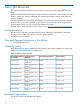
Table 29 EFI Commands EFI Shell Command BCH Command Equivalent (PA-RISC) BCH Command Parameters (PA-RISC) Definition These commands are found in all other menus info boot Boot [PRI|HAA|ALT|] Boot from specified path help HElp [
Table 29 EFI Commands (continued) EFI Shell Command BCH Command Equivalent (PA-RISC) BCH Command Parameters (PA-RISC) Definition lanaddress LanAddress Display core LAN station address info mem Memory Display memory information info cpu PRocessor Display processor information errdump clear CLEARPIM Clear (zero) the contents of PIM mm MemRead pdt page deallocation table (pdt) errdump mca processor internal memory (PIM) SERvice errdump cmc [] [] Read memory locations
or will inform the user that the functionality no longer exists. As a shortcut, enter help followed by bch and a BCH command name to go straight to that command.
Example 2 help command Shell> help List of classes of commands: boot configuration devices memory shell scripts -- Booting options and disk-related commands -- Changing and retrieving system information -- Getting device, driver and handle information -- Memory related commands -- Basic shell navigation and customization -- EFI shell-script commandsType "help" followed by a class name for a list of commands in that class Type "help" followed by command name for full documentation Example 3 help bch comman
Example 5 help cpuconfig command Shell> help cpuconfig CPUCONFIG [cpu] [on|off] cpu Specifies which cpu to configure on|off Specifies to configure or deconfigure a cpu Notes: 1.
boottest off boottest [test] boottest [test] [on|off] Skip all tests (for a faster boot time) Displays status of specific Speedy Boot bit Sets or clears a specific Speedy Boot bit Parameters [test] Each test can be set or cleared: booting_valid Enable/disable system firmware response to BOOTING bit. If OS Speedy Boot aware set to on. early_cpu Enable/disable early CPU selftests. late_cpu Enable/disable late CPU selftests. platform Enable/disable system board hardware tests.
state is entered and is different from the current state of a processor, its status changes on the next boot. The last remaining configured processor in a server cannot be deconfigured. Example 8 cpuconfig command Shell> cpuconfig PROCESSOR INFORMATION # of CPU Logical Slot CPUs Speed ----------------0 1 1 GHz 1 1 1 GHz L3 Cache Size ---1.5 MB 1.5 MB L4 Cache Size ----None None Family/ Model (hex.) Rev --------1F/01 B1 1F/01 B1 Processor State ---------Active Active Family/ Model (hex.
Example 11 conconfig 2 primary command To change primary operating system console Shell> conconfig 2 primary CONSOLE CONFIGURATION Index Status Type Device Path ----- ------ -------------1 NC Serial Acpi(PNP0501,0) 2 P Serial Acpi(HWP0002,0)/Pci(1|1) 3 S VGA Acpi(HWP0002,0)/Pci(4|0) Example 12 conconfig 3 off command To disable a console Shell> conconfig 3 off CONSOLE CONFIGURATION Index Status Type Device Path ----- ------ -------------1 NC Serial Acpi(PNP0501,0) 2 P Serial Acpi(HWP0002,0)/Pci(1|1 3 NC VG
Parameters mca cpe cmc init la clear dumps the Machine Check Abort error log dumps the Corrected Platform Error log dumps the Corrected Machine Check log dumps the Initialization log dumps the Logic Analyzer log erases all of the logs (mca, cpe, cmc, init, la) Operation If a user enters no parameters, the usage is displayed. Otherwise, the specified error log displays. Adding -n to the clear parameter disables the confirmation prompt (Access the errdump command from the System Configuration menu).
Example 14 info all command Shell> info all SYSTEM INFORMATION Date/Time: Oct 31, 2003 22:03:39 (20:03:10:31:22:03:39) Manufacturer: hp Product Name: server BL870c Product Number: A9901A Serial Number: MYJ3350026 UUID: 48B4F371-E34C-11D6-A8D6-07A8C14CB68B System Bus Frequency: 200 MHz PROCESSOR MODULE INFORMATION CPU Slot # of Logical CPUs ---0 1 ------1 1 Speed L3 Cache Size L4 Cache Size Family/ Model (hex.) Rev Processor State -------1 GHz 1 GHz -----1.5 MB 1.
Selftest --------early_cpu late_cpu platform chipset io_hw mem_init mem_test Setting -------------Run this test Run this test Run this test Run this test Run this test Run this test Run this test LAN Address Information: LAN Address ----------------Mac(00306E4C4F1A) *Mac(00306E4C0FF2) Path ---------------------------------------Acpi(HWP0002,0)/Pci(3|0)/Mac(00306E4C4F1A)) Acpi(HWP0002,100)/Pci(2|0)/Mac(00306E4C0FF2)) FIRMWARE INFORMATION Firmware Revision: 1.10 [4341] PAL_A Revision: 7.31/5.
Example 15 info cpu command Shell> info cpu PROCESSOR MODULE INFORMATION # of Logical CPUs ------1 1 CPU Slot ---0 1 Speed -------1 GHz 1 GHz L3 Cache Size -----1.5 MB 1.5 MB L4 Cache Size -----None None Family/ Model (hex.
Example 18 info boot command Shell> info boot BOOT INFORMATION Monarch CPU: Current Preferred Monarch Monarch Possible Warnings -------- -------------------------0 0 AutoBoot: on - Timeout is : 7 SEC Boottest: boottest Settings Default Variable OS is not speedy boot aware.
Example 19 ioconfig command Shell> ioconfig Deconfigure or reconfigure IO components or settings IOCONFIG [fast_init | wol [on | off]] fast_init Specifies device connection policy setting mps_optimie Specifies PCIe optimization setting wol Specifies System Wake-On-LAN setting on | off Specifies to configure or deconfigure a feature or component Note: 1. If fast_init is enabled, firmware will connect only the minimum set of devices during boot.
Syntax monarch Parameters specifies a cpu Operation If specified with no parameters, monarch displays the Monarch processor for the server. Specifying a processor number alters the preferred Monarch processor. None of these changes takes affect until after a reboot.
Example 22 pdt command Shell> pdt PDT Information Last Clear time: PDT has not been cleared Number of total entries in PDT: 50 Number of used entries in PDT: 0 Number of free entries in PDT: 50 Number of single-bit entries in PDT: 0 Number of multi-bit entries in PDT: 0 Address of first multi-bit error: x0000000000000000 Example 23 pdt clear command Shell> pdt clear Are you sure you want to clear the PDT? [y/N] y Shell> Shell> pdt PDT Information Last Clear time: 10/21/01 5:00p Number of total entries in P
Example 24 sysmode command Shell> sysmode System Mode: NORMAL Shell> sysmode admin You are now in admin mode. Shell> sysmode service You are now in service mode.
1. At the EFI Shell prompt, enter the info io command to map the parameters for all PCI cards installed in the server. A list of all the devices that are installed in the server blade and managed by EFI drivers displays.
Shell> devtree Device Tree Ctrl[04] Ctrl[0A] Ctrl[12] Ctrl[13] Ctrl[14] Ctrl[15] Ctrl[48] Ctrl[83] Ctrl[16] Ctrl[49] Ctrl[0B] Ctrl[17] Ctrl[18] Ctrl[19] Ctrl[4B] Ctrl[0C] Ctrl[0D] Ctrl[0E] Ctrl[1A] Ctrl[1B] Ctrl[36] Ctrl[37] Ctrl[31] Ctrl[32] Ctrl[30] Ctrl[1C] Ctrl[32] Ctrl[30] Ctrl[33] Ctrl[34] Ctrl[35] Ctrl[31] Ctrl[32] Ctrl[30] Ctrl[44] Ctrl[46] Acpi(HWP0002,0) Usb Open Host Controller Usb Open Host Controller Acpi(HWP0002,0)/Pci(1|2) PCI IDE/ATAPI Controller DW-28E FAT File System [FAT32] 118 MB Acpi(H
This listing shows which driver controls which device (controller). In the above example, the interface information is shown highlighted bold. You can tell the information is for this interface because the values shown for Ctrl-17 and 18 are the controller handles for the interface 2 channels (from the information displayed by the devtree command). NOTE: The EFI driver’s handle values change on every boot.
PCI Device, and PCI Function to the Bus #, Dev #, and Fnc # values from the info io command. CAUTION: Do not change the value for any of these fields on the Adapter Properties screen: • Auto Termination • Parity • Bus Scan Order • Spinup Delay (Secs) Changing any of these fields can cause unpredictable results.
Using the Boot Option Maintenance Menu This menu enables you to select console output and input devices as well as various boot options. In all menus, select: • Help to display the help available for the command • Exit to return to the main Boot Options Maintenance menu • Enter to select an item after using the arrow keys to highlight the item • Save Settings to NVRAM to save your changes NOTE: The options shown here are examples.
• Removable Media Boot allows you to boot from a removable media drive (CD/DVD drive). This option does not support booting from a specific file on a specific removable media disc. • The two Load Files are the EFI Shell and the LAN. Add a Boot Option Use this option to add items to the EFI boot menu. This option displays the file systems that are on your server and lets you browse these file systems for applications or drivers that are executable. Executable files end with the .efi extension.
For example, if you normally boot using a configuration on your LAN but would like to boot from a local hard drive if the LAN is unavailable, move the LAN boot option to the top of the list, followed by the hard drive boot option. The menu lists boot options that currently exist in the main EFI Boot Manager menu. Change the priority of the items by moving them up or down in the list: • Press U to move an option up. • Press D to move an option down.
Interrupting the timeout during the countdown stops the Boot Manager from loading any boot options automatically. If there is no countdown, boot options must be selected manually. • To set the auto boot timeout value, in seconds, select Set Timeout Value and enter the desired value. • To disable the timeout function, select Delete/Disable Timeout. NOTE: When this option is selected, the server does not automatically boot. The server stops at the EFI boot menu and waits for user input.
This option displays the console devices on your server. This normally includes a standard keyboard and mouse, and a serial port for receiving output from a terminal emulation package on a laptop. Several different terminal emulation protocols are supported. • When changing serial devices, changes must be made to Output, Input, and Error menus for proper operation. NOTE: Some Operating Systems support multiple input devices, such as a simultaneous serial and keyboard input.
• Reset Configuration to Default lets you restore server settings to their original configuration • Help displays additional information about the available options • Exit returns to the EFI startup menu Security/Password Menu You can set administrator and user passwords to provide different levels of access to the system firmware. Resetting Passwords If you forget your passwords, they can be reset using an iLO 2 MP command. • Run the MP BP command to reset the iLO 2 MP and reset the password.
Index A access panel removing the left , 30 removing the left access panel, 118 removing the right , 29 removing the right access panel, 116 replacing the left access panel, 119 replacing the right access panel, 117 accessing iLO 2 MP, 44 ACPI pathing, 107 adapter slot number, determining with info command, 165 adapter path determining with info command, 165 adapter properties screen, 59 adding Windows to the boot options list, 81 air baffle DIMM, 121 antistatic wrist strap, 26 array screen create, 61 manag
disk drive blank removing, 112 replacing, 113 drvcfg command EFI configurable components, displaying, 166 EFI driver handle, determining, 167 EFI Setup Utility, starting, 167 drvcfg utility, 57 E EFI accessing from iLO 2 MP, 52 boot manager, 53 capable devices and controller handles, displaying, 165 commands, 57, 147 configurable components, displaying, 166 driver firmware update, 56 driver handle, determining, 167 overview, 146 saving configuration settings, 53 shell paths, 169 viewing VPD and driver info
integrated Lights Out Management Processor see iLO 2 MP internal components, 120 internal health LED, 95 internal USB port, 17 L LAN LEDs, 97 LEDs boot process, 97 front panel, 21, 94 internal health, 95 LAN, 97 NIC, 97 NICs, 94, 96 SAS disk drive, 21, 96 server health, 95 unit identification (UID), 91, 95 left access panel replacing, 41 Linux shutting down, 88 Linux (Red Hat) booting, 86 Linux (SuSE) booting, 87 load order DIMMs, 36 lock-step mode, 122 M manage array screen, 64 Management Processor see i
remote access allowing, 51 configuring, 50 disabling, 51, 52 securing, 49 removing DIMMs, 121 disk drive blank, 112 front panel, 130 hard drive blank, 28 left access panel, 30, 118 mezzanine card, 134 processor, 125 right access panel, 29, 116 SAS backplane, 129 SAS disk drive, 111 server battery, 133 server blade from enclosure, 114 system board, 138 TPM, 136 replacing DIMMs, 121, 122 disk drive blank, 113 front panel, 132 left access panel, 41, 119 mezzanine card, 135 processor, 127 right access panel, 40
removing, 138 replacing, 140 system boot options, 71 system configuration menu, 173 system event log, 90, 101, 102 T tools required, 27, 111 TPM location, 137 removing, 136 replacing, 137 troubleshooting advanced, 93 basic, 90 BMC and MP firmware, 108 communications modules, 107 environment, 109 firmware, 108 management subsystems, 108 memory, 106 methodology, 90 online support, 110 overview, 89 phone support, 110 processors, 105 reporting problems to HP, 109 SBA, 107 system console, 109 using the iLO 2 MP