hp Integrity cx2600 Installation Guide Regulatory Model Number: RSVLA-0303-DC Version 3.0 Manufacturing Part Number: AB216-90001 March 2004 U.S.A. © Copyright 2004 Hewlett-Packard Development Company, L.P..
Legal Notices Copyright Notices. © Copyright 2004 Hewlett-Packard Development Company, L.P. The information contained herein is subject to change without notice. The only warranties for HP products and services are set forth in the express warranty statements accompanying such products and services. Nothing herein should be construed as constituting an additional warranty. HP shall not be liable for technical or editorial errors or omissions contained herein.
Contents 1. About This Document What’s in This Document . . . . . . . . . . . . . . . . . . . . . . . . . . . . . . . . . . . . . . . . . . . . . . . . . . . . . . . . . . . . . . Typographical Conventions . . . . . . . . . . . . . . . . . . . . . . . . . . . . . . . . . . . . . . . . . . . . . . . . . . . . . . . . . . . Related Documents . . . . . . . . . . . . . . . . . . . . . . . . . . . . . . . . . . . . . . . . . . . . . . . . . . . . . . . . . . . . . . . . . . . HP Encourages Your Comments . . . .
Contents Introduction . . . . . . . . . . . . . . . . . . . . . . . . . . . . . . . . . . . . . . . . . . . . . . . . . . . . . . . . . . . . . . . . . . . . . . . . Troubleshooting Methodology . . . . . . . . . . . . . . . . . . . . . . . . . . . . . . . . . . . . . . . . . . . . . . . . . . . . . . . . . . Using the Front Panel Power Button. . . . . . . . . . . . . . . . . . . . . . . . . . . . . . . . . . . . . . . . . . . . . . . . . . . If the Server Will Not Power Up . . . . . . . . . . . . . . . . .
Figures Figure 2-1. hp Integrity cx2600 Server . . . . . . . . . . . . . . . . . . . . . . . . . . . . . . . . . . . . . . . . . . . . . . . . Figure 2-2. hp Integrity cx2600 Server (front view). . . . . . . . . . . . . . . . . . . . . . . . . . . . . . . . . . . . . . Figure 2-3. hp Integrity cx2600 Server (rear view) . . . . . . . . . . . . . . . . . . . . . . . . . . . . . . . . . . . . . . Figure 3-1. Chassis Ground Lug . . . . . . . . . . . . . . . . . . . . . . . . . . . . . . . . . . . . . . . . . .
Figures 6
1 About This Document This document describes how to install your hp Integrity cx2600 Server, Regulatory Model Number: RSVLA-0303-DC. The document printing date and part number indicate the document’s current edition. The printing date will change when a new edition is printed. Minor changes may be made at reprint without changing the printing date. The document part number will change when extensive changes are made.
About This Document Related Documents Related Documents The HP Server Documentation CD-ROM has been provided with your server. It contains a complete documentation set for the server, including localized versions of key documents. Included on the CD-ROM are the Site Preparation and Operations and Maintenance guides, which contain in-depth troubleshooting, installation, and repair information. The CD will autorun when you insert it into a Windows workstation, or, point your browser at the index.
About This Document Where to Get Help • The product number of your server. This can be found on the identification label, which is found at the front of the unit (typically A6837B A6838B, and so on). • The serial number of your server. This can be found on the identification label. Step 3.
About This Document Where to Get Help 10 Chapter 1
2 Server Overview and Unpacking Server Overview The hp Integrity cx2600 Server (Regulatory Model No. RSVLA-0303-DC) is a 1- or 2-way, IA-64, carrier grade server based on the Itanium processor family architecture. This server is NEBS level-3 compliant and is intended for Telco users. The hp Integrity cx2600 Server accommodates 1 or 2 processors, from 4 to 12 DIMMs (providing 1 to 24 GB of memory), and internal peripherals including up to 3 disks and a CD/DVD-ROM.
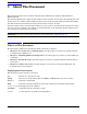
Server Overview and Unpacking Server Overview Figure 2-2 hp Integrity cx2600 Server (front view) hp integrity cx2600 1 2 3 4 LAN System chasfront Figure 2-3 hp Integrity cx2600 Server (rear view) Fault DC Out Fault DC In DC Out DC In rearview 12 Chapter 2
Server Overview and Unpacking Unpacking the Server Unpacking the Server Hewlett-Packard shipping containers protect their contents under normal shipping conditions. After the equipment arrives, carefully inspect each carton for signs of shipping damage. If damage is found, document the damage with photographs and contact the transport carrier immediately. If the equipment has any damage, a damage claim form must be obtained from the shipping representative.
Server Overview and Unpacking Unpacking the Server 14 Chapter 2
3 Installing Additional Components Safety Information This chapter describes installing additional or optional hardware to your hp Integrity cx2600 Server. Follow the procedures listed below to ensure safe handling of components and to prevent harm to both you and the HP Server: • Use an antistatic wrist strap and a grounding mat, such as those included in the Electrically Conductive Field Service Grounding Kit (HP 9300-1609). • Handle accessory boards and components by the edges only.
Installing Additional Components Accessing a Rack Mounted Server Installing Components When the Server is in a Rack Power supplies, disks and fans can be installed when the server is fully inserted into a rack. Only front and rear access is required. Internal components can be accessed by removing the top cover. Proceed as follows: WARNING Hazardous energy is present inside the HP Server. Always remove power from the server before working inside the unit.
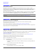
Installing Additional Components Accessing a Rack Mounted Server Figure 3-1Chassis Ground Lug Chassis Ground Lug chasgndlug WARNING Do not attempt to lift the server alone. The server may weight as much as 32 kilograms (70 lbs). Serious injury may result if this warning is not observed. Step 5. If the server is slide-mounted, slowly pull the chassis forward (or push from the rear) to extend the chassis from the rack. The server is fully extended when the rail clips are locked in place.
Installing Additional Components Installing Disk Drives Step 5. Replace or tighten (as appropriate) the screws that fasten the server to the rack. Installing Disk Drives The supported configuration of an hp Integrity cx2600 Server includes 1, 2 or 3 Low-Voltage-Differential (LVD), hot-plug disk drives. If any of the three disk drives are not installed a disk filler must be installed in the disk location. Hot-plug disk drives are located at the front of the server.
Installing Additional Components Installing Disk Drives CAUTION The disk drives in the hp Integrity cx2600 Server are not hot-swappable. They are merely hot-pluggable. A manual software procedure may be required in order to safely remove or insert disk drives while the system is running. To avoid damage to the hard drives: Refer to the documentation provided with the disk drive for additional information about removing and inserting a drive.
Installing Additional Components Hot-Swap Power Supply Units Step 4. Press the release lever until it is flush with the front of the server. You will hear it click as it locks into position. Step 5. If the operating system was stopped in step 1, reset the system to the EFI Boot Maintenance Menu, to rescan the hard drives. Step 6. If the operating system was stopped in step 1, use the EFI shell map command to verify that the newly inserted drive has been correctly installed.
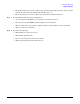
Installing Additional Components Hot-Swap Power Supply Units Figure 3-4 Hot-Swap Power Supplies chaspsxtnd Power Supply 1 Power Supply 2 Removing and Replacing a Hot-Swap Power Supply A power supply can be replaced while the server is installed in a rack, with the server operating normally. Removal and installation of a power supply will have no effect on operations if the other power supply is functioning correctly.
Installing Additional Components Hot-Swap Power Supply Units Figure 3-5 Removing a Hot-Swap Power Supply Mounting Screws chaspsxtnd Cable Clamp Handle Step 1. If rack-mounted, it may be necessary to extend a slide-mounted server out from the rack for better access. If needed, slide the server out to the fully extended position. Step 2. Remove power from the power supply being replaced.
Installing Additional Components Front Grill and Top Cover Step 8. Pull the power supply from the server chassis by pulling the curved handle. Step 9. Orient the replacement power supply such that the securing screws are aligned with the corresponding holes in the server chassis. Gently push the power supply into position. Step 10. When the power supply is fully inserted into the server chassis, tighten the two mounting screws to secure the power supply in place. Step 11.
Installing Additional Components Front Grill and Top Cover Observe all ESD safety precautions while performing this procedure. Failure to follow ESD safety precautions could result in damage to the server. Figure 3-7 Removing the Front Grill chasfrntoff Captive Screws Removing the Front Grill You must remove the front grill for access to the front mounted fans or the optical drive. To remove the front grill, perform the following steps: Step 1.
Installing Additional Components Front Grill and Top Cover Removing the Top Cover Figure 3-8 Removing the Top Cover Cover Holding Screw Slots for Tabs in Cover (2 each side) Cover Tabs Slots for Tabs ESD Ground Jack (Connect wrist strap here) topupwguide To remove the top cover, perform the following steps: Chapter 3 25
Installing Additional Components Front Grill and Top Cover WARNING Hazardous energy is present within the server when power is applied. Do not remove the server top cover without first turning off and disconnecting power. Always replace the top cover before turning the system on. Step 1. Turn off and disconnect system power. Disconnect power at the DC source end of the power cable(s), using the disconnect device that is part of the rack or facility power system. Step 2.
Installing Additional Components Hot-Swap Chassis Fan Units Hot-Swap Chassis Fan Units There are five hot-swap chassis fan units in the HP Server. Fan units 1, 2, 3 and 4 are accessible from the front of the chassis. Fan unit 5 is accessible from the rear of the chassis. Fan units 1, 2, 3 and 4 are identical and interchangeable. If a fan failure is total (both rotors), or if the fan has been removed from the chassis for more than 30 seconds, a system will log the event as a critical error.
Installing Additional Components Hot-Swap Chassis Fan Units Removing and Replacing a Front Panel Hot-Swap Fan Figure 3-9 Removing a Front Panel Hot-Swap Fan Fan 2 Fan 1 Fan 3 Fan 4 chasfan1xtnd Captive Screws The server does not need to be removed or extended from the rack to allow fan replacement. To remove and replace a hot-swap fan from the front of the server chassis, perform the following steps: Step 1. Remove the front grill. Refer to “Removing the Front Grill” on page 24. Step 2.
Installing Additional Components Hot-Swap Chassis Fan Units Removing and Replacing a Rear Panel Hot-Swap Fan Figure 3-10 Removing a Rear Panel Hot-Swap Fan Fan 5 Mounting Screws chasfan5xtnd To remove and replace the hot-swap fan from the rear of the server chassis, perform the following steps: NOTE The server does not need to be removed from the rack to allow fan replacement. Step 1. If rack-mounted, it may be necessary to extend a slide-mounted server out from the rack for better access.
Installing Additional Components Hot-Swap Chassis Fan Units Step 2. Using an ACX-15 torx screwdriver, loosen the two captive screws that secure the fan unit to the server chassis. CAUTION Hot-swapping a fan can interrupt system operation. If you are hot-swapping a fan assembly and the system is operating normally, hot-swapping the fan in less than 30 seconds will eliminate the requirement for a system reboot.
Installing Additional Components PCI Card Installation PCI Card Installation The hp Integrity cx2600 Server has four 64-bit, 133 MHz PCI-X accessory card sockets located in a removable card cage. The PCI card cage must be removed before PCI cards can be removed or installed. The following sections remove and open the card cage, remove and install PCI cards, and reinstall the card cage. Removing the PCI Card Cage Assembly To remove the PCI card cage assembly, perform the following steps: Step 1.
Installing Additional Components PCI Card Installation Figure 3-11Removing the PCI Card Cage PCI Card Cage Release Lever chaspciccdwn Step 6. Place the card cage on an ESD-protected work surface. Step 7. Orient the card cage such that PCI card connectors (within the card cage) are at the bottom, when viewed through the open side of the card cage, and cards can be removed by lifting them from the sockets. Step 8.
Installing Additional Components PCI Card Installation CAUTION Observe all ESD safety precautions while performing this procedure. Failure to follow ESD safety precautions could result in damage to the server. Step 3. If a cable will block card removal, or if it is connected to the card to be removed, disconnect the cable(s) from card connector(s) at this time. Step 4. Using an ACX-15 torx screwdriver, remove the retaining screw that secures the card in place. See Figure 3-12.
Installing Additional Components PCI Card Installation Step 2. Remove the cover from the PCI card cage. CAUTION Observe all ESD safety precautions while performing this procedure. Failure to follow ESD safety precautions could result in damage to the server. Step 3. If a blank panel is installed at the end of the card cage (for the card position/socket which will be used), remove the blank panel. Step 4.
Installing Additional Components PCI Card Installation Figure 3-13Installing the PCI Card Cage PCI Card Cage Release Lever chaspciccup Step 3. Press the release lever down (into position) to lock the card cage in place in the chassis. Step 4. Reinstall the chassis top cover. Refer to “Replacing the Top Cover” on page 26. Step 5. Reconnect rear panel cables, and turn on the system. Step 6. Run info io at the EFI shell to verify that the PCI card(s) has been correctly installed.
Installing Additional Components Installing Processors and Memory Installing Processors and Memory This section provides information about removing and installing processors and memory. The processors and memory are located on the system board and are accessible after removing the top cover and air guides. Processor 0 (CPU 0) is located closer to the chassis side panel and processor 1 (CPU 1) is located closer to the DIMM sockets. (See Figure 3-14.
Installing Additional Components Installing Processors and Memory WARNING Voltages and hazardous energy can be present at various locations within the server whenever a power source is connected. This hazard is present even when the power switch is in the off position. Ensure that the system is powered down and all power sources have been disconnected from the server prior to performing the following procedures. Failure to observe this warning could result in personal injury or damage to equipment.
Installing Additional Components Installing Processors and Memory Step 7. Loosen the power module mounting screws and disconnect the module from its processor by sliding it toward the back of the chassis. Figure 3-16Disconnecting the Power Module Power Module Mounting Screws Power Module Cable cpu1wpm1 Processor Fan Turbo Fan Power Cable Step 8. Remove the CPU power module from the server chassis. Step 9. Disconnect the turbo fan power cable. Step 10.
Installing Additional Components Installing Processors and Memory Figure 3-17Loosen the Turbo Fan Heatsink Screws Sequencing Retainer Plate Insert Processor Tool Here cputopvue Step 12. Insert the processor tool into the hole that runs down through the edge of the turbo fan heatsink. Figure 3-18Unlocking the Processor Insert Processor Tool Here Unlocked Locked cpusoclock Step 13. Unlock the processor locking mechanism by rotating the tool counterclockwise 180 degrees. (See Figure 3-18). Step 14.
Installing Additional Components Installing Processors and Memory Installing a Processor The following procedure is applicable to installation of processor 0 or processor 1. Processor 0 must be installed before installing processor 1. Proceed as follows: NOTE Installation instructions are provided with replacement processors. Read those instructions carefully. Changes in processor design (and installation) may have occurred since this procedure was written.
Installing Additional Components Installing Processors and Memory Figure 3-19Installing the Turbo Fan and Processor Assembly Screw 1 (not shown) (Tighten first) Insert Processor Tool Here Screw 3 (Tighten third) Screw 4 (Tighten last) Screw 2 (Tighten second Locator Post Locator Post Locator Hole Locator Hole cpu1noppm3 Step 9. Use the special processor tool shipped with processor assemblies to lock the processor in place on the system board.
Installing Additional Components Installing Processors and Memory Step 17. If necessary, reinstall the chassis in the rack. Refer to “Install the Server into a Rack” on page 17. Step 18. Reconnect power and system cables to rear panel connectors. Step 19. Turn on the system. Step 20. Run info cpu at the EFI shell prompt to verify that the processor has been installed correctly.
Installing Additional Components Installing Processors and Memory Figure 3-20Memory Airflow Guide Memory Airflow Guide chascvroff Step 6. Locate the DIMM(s) to be removed. (See Figure 3-21).
Installing Additional Components Installing Processors and Memory Figure 3-21DIMM Slots 0B 1B 4B 5B 2B 3B 0A 1A 4A 5A 2A 3A sysbrd1cpu Step 7. Press down on the DIMM retainer clips on either end of the DIMM connector, and lift the DIMM from the system board socket. Step 8. If the removed DIMM is functional, store it for future use. (Store the DIMM in a static-free container.) Step 9. Repeat steps 6 through 8 for each DIMM to be removed. Step 10.
Installing Additional Components Installing Processors and Memory Failure to observe this warning could result in personal injury or damage to equipment. NOTE DIMMs must be installed in matched groups of four. DIMM sizes can vary between quads, but all DIMMs within a quad must be identical. Step 1. If rack mounted, extend a slide-mounted server out from the rack until it stops. Refer to “Accessing a Rack Mounted Server” on page 15. Step 2. Turn off the system. Disconnect all external cables. Step 3.
Installing Additional Components Installing Processors and Memory Figure 3-22Inserting DIMM into a DIMM Socket dimm_sokt Step 9. Snap the socket retainer clips into place, ensuring that the DIMM is locked in the socket. Step 10. Repeat steps 6 through 9 for each DIMM to be installed. Step 11. Set the memory airflow guide in position and reinstall the top cover.
4 Troubleshooting Introduction This chapter presents troubleshooting information. Basic tips for start-up problems are presented, audio cues and LED indicators are described and interpreted, and error messages (and how to retrieve them) are described. In addition, problems that are associated with I/O functions and paths are discussed here. Troubleshooting Methodology WARNING Always disconnect the power cords and unplug telephone cables before removing the server cover.
Troubleshooting Troubleshooting Methodology Offline troubleshooting programs are available on the resource CD that is shipped with your HP Server. To troubleshoot your system you should be familiar with the Offline Diagnostics Environment (ODE) which runs in the Extensible Firmware Interface (EFI). Descriptions and user information about offline troubleshooting tools are available at http://docs.hp.com. The offline tools are available for downloading at http://software.hp.com.
Troubleshooting Troubleshooting Methodology If EFI Is Not Available If it is not possible to reach the EFI (from either the main disk partition or CD), then you must use the following tools to help solve your problem: • Front panel LEDs (page 52) • Management processor (MP) (page 62) — Console messages — System event logs (SEL) If the Operating System Will Not Boot If your operating system will not boot, but you are able to reach the EFI (from either the main disk partition or CD), then use the followi
Troubleshooting Troubleshooting Using Beep Codes (System e-buzzer) If DVD Problems Occur DVD problems that occur during installation are usually related to faulty connections. If you are experiencing DVD problems, proceed as follows: • Remove and reinsert the disk. • Replace the disk. • Remove and reinstall the DVD drive. Check that connectors are fully engaged. • Replace the DVD drive.
Troubleshooting Troubleshooting Using LED Indicators NOTE The error message and identifying information can be sent via telephone line to an authorized help desk or to an HP Support facility. This telephone signal can be decoded to identify the server by model and serial number, and to help identify the error. To send this signal to HP Support via telephone, just hold the telephone next to the Locator button on the server front panel while the system is booting.
Troubleshooting Troubleshooting Using LED Indicators Front Panel LEDs The front panel LEDs show you the system status at a glance. They include four diagnostic LEDs, and the System, LAN, and power LEDs. The front panel LEDs are listed in the following tables, together with system status and/or probable cause descriptions of likely system failures.
Troubleshooting Troubleshooting Using LED Indicators Table 4-2 Front Panel LED Definitions (Continued) LED/ Button System State Flash Rate Color Description Diag LEDs (1 thru 4) - - - Display system error condition (when System LED is flashing yellow) or fault condition (when System LED is flashing red). Refer to Table 4-3 for error code information. LAN LED Off Off N/A The system is off (no power to LAN circuits) or hardware failure.
Troubleshooting Troubleshooting Using LED Indicators Table 4-3 Diag 1 LED Diagnostic LED Displays and Meanings Diag 2 LED Diag 3 LED Diag 4 LED System LED Description Off Off Green Red Flashing Yellow Fan 3 warning. BMC is reporting that one fan rotor is turning more slowly than expected (or stopped). Investigate problem at the first opportunity. Off Green Off Red Flashing Yellow Fan 2 warning. BMC is reporting that one fan rotor is turning more slowly than expected (or stopped).
Troubleshooting Troubleshooting Using LED Indicators Table 4-3 Diag 1 LED Diagnostic LED Displays and Meanings (Continued) Diag 2 LED Diag 3 LED Diag 4 LED System LED Description Red Red Green Off Flashing Yellow CPU 0 temperature warning. Check for blockages. Investigate the problem at the first opportunity. Red Red Red Red Flashing Yellow Undefined error condition (warning only). Check the SEL for information. Off Off Green Red Flashing Red Fan 3 failure.
Troubleshooting Troubleshooting Using LED Indicators Table 4-3 Diag 1 LED Diagnostic LED Displays and Meanings (Continued) Diag 2 LED Diag 3 LED Diag 4 LED System LED Description Green Green Off Red Flashing Red Fan 4 failure. BMC is reporting that both fan rotors are turning more slowly that expected (or stopped). Replace the fan, fan control board, or system board. Green Green Green Red Flashing Red CPU 0 turbofan failure. Replace CPU 0, the CPU power module, or the system board.
Troubleshooting Troubleshooting Using LED Indicators Table 4-3 Diagnostic LED Displays and Meanings (Continued) Diag 1 LED Diag 2 LED Red Red Diag 3 LED Diag 4 LED Red Red System LED Description Flashing Red Undefined error condition (catastrophic failure). Check the SEL for information. Rear Panel LEDs The rear panel LEDs show you LAN and power supply status at a glance. The rear panel LEDs are listed in the following table, together with descriptions of LAN and power status indications.
Troubleshooting Error Messages and Event Logs Table 4-4 Rear Panel LED Definitions (Continued) LED/ Button Color Description Power Supply DC Out Green Lit when a power supply is operating normally. Indicates that DC power is being supplied to server circuits. Power Supply DC In Green Lit when power (–36 to –72 VDC) is being supplied to the power supply. Indicates that source power is available. Gigabit LAN Gbit LED (top) Green When off, no 1000 Mbps link has been detected.
Troubleshooting Error Messages and Event Logs EFI Error and Warning Messages EFI error and warning messages are displayed on the console as part of the boot process. They can also be retrieved using the EFI command: info warnings. Table 4-5 lists the error messages that may be encountered during installation. Refer to the hp Integrity cx2600 Operation and Maintenance Guide for additional information.
Troubleshooting Error Messages and Event Logs Table 4-5 EFI Error and Warning Messages (Continued) Error Number Message Description/Solution 21 BMC token write error during NVM write through Communication with the BMC failed. Replace the system board. 22 Error reading BMC token on upload to NVM Communication with the BMC failed. Replace the system board. 23 Error reading BMC first boot token Communication with the BMC failed. Replace the system board. 24 Primary FIT failed Reflash firmware.
Troubleshooting Error Messages and Event Logs Table 4-5 EFI Error and Warning Messages (Continued) Error Number Message Description/Solution 40 CPUs installed with mixed cache sizes Check processor installation and match CPU part numbers. CPUs must be identical. 40 CPUs installed with mixed cache sizes Check processor installation and match CPU part numbers. CPUs must be identical. 41 CPUs installed with mixed steppings Check processor installation and match CPU part numbers.
Troubleshooting Error Messages and Event Logs Table 4-5 EFI Error and Warning Messages (Continued) Error Number Message 59 FRU information version error Description/Solution Replace the FRU which was reported. If the error message is repeated, contact the HP Support center for assistance. Event Logs The System Event Log (SEL) and Forward Progress Log (FPL), Live Event Log, and Boot logs are available via the MP. The SEL records system events that are of major importance to system operations.
Troubleshooting Troubleshooting Using Offline Support Tools Disk and I/O Path Logging Some failures result in I/O path logging. These paths help to indicate the source of the error and may be included in the error message or logged into console or event logs. The following table describes the disk drive and PCI slot paths for your HP Server.
Troubleshooting Troubleshooting Using Offline Support Tools E-Diag Tools E-DiagTools is used to evaluate the hardware integrity of your HP Server. To access E-DiagTools from the IPF Offline Diagnostic CD, perform the following steps: Step 1. Power on your HP Server and insert the IPF Offline Diagnostics CD into the DVD-ROM tray. Step 2. Do not permit the server to boot into an operating system and at the EFI Boot Manager, select EFI shell. Step 3.
Troubleshooting Troubleshooting Using Offline Support Tools To access these logs type in at the shell>command line prompt: errdump mca errdump cmc errdump cpe Hypothetical Troubleshooting Scenario The following describes a hypothetical troubleshooting scenario that might occur with your hp Integrity cx2600 Server. 1. This is the entry point to the troubleshooting process. Here, you pick from a set of symptoms, ranging from very simple (system LED is blinking) to the most difficult (MCA has occurred).
Troubleshooting Troubleshooting Using Offline Support Tools 66 Chapter 4
5 Cable Connections Input Power The hp Integrity cx2600 server comes with two power supplies installed: each powered from its own power cable. The input for each connector is rated for –48 VDC (–40 to –72 VDC) at up to 15 amps (max.). (See Figure 5-2 for power supply terminals/connections.) The server will function normally with only one power supply installed, but N+1 redundancy requires that both power supplies be used during normal operations.
Cable Connections Wire Selection and Terminal Lugs for Connection of DC Power Wire Selection and Terminal Lugs for Connection of DC Power WARNING Always check that the power cable is not connected to a power source before attempting to connect the power cable to server power supply terminals. Failure to observe this warning could result in personal injury or damage to equipment.
Cable Connections Core I/O Connections Core I/O Connections The locations of interface connectors on the hp Integrity cx2600 Server rear panel are shown in Figure 5-2.
Cable Connections Core I/O Connections Management Processor (MP) The management processor is an independent support system for the server. It provides a way for you to connect to a server and perform administration or monitoring tasks for the server hardware. The management processor controls power, reset, transfer of control (TOC) capabilities, provides console access, displays and records system events, and can display detailed information about the various internal subsystems.
Cable Connections Core I/O Connections If the terminal is a PC using Reflection 1, check or change these communications settings by performing the following steps: Step 1. From the Reflection 1 Main screen, pull down the Connection menu and select Connection Setup. Step 2. Select Serial Port. Step 3. Select Com1. Step 4. Check the settings and change, if required. Go to More Settings to set Xon/Xoff. Click OK to close the More Settings window. Step 5. Click OK to close the Connection Setup window. Step 6.
Cable Connections Core I/O Connections NOTE On initial system installation, the MP has two default user accounts. They are: 1. Administrator level user; login=Admin, password=Admin (both are case sensitive). 2. Operator level user; login=Oper, password=Oper (both are case sensitive).
Cable Connections Core I/O Connections NOTE The value in the “IP address” field is set at the factory. The customer must provide the actual management processor LAN IP address. Step 3. The current lc data is displayed. When prompted to enter a parameter name, A to modify All, or Q to Quit, enter A to select all parameters. Step 4. The current IP address is displayed. When prompted to enter a new value or Q, enter the new IP address. Step 5. The current host name is displayed.
Cable Connections Core I/O Connections The LC Command Screen LC commands: MP:CM> lc -ip 127.0.0.1 -host uninitialized -subnet 255.255.255.0 -gate 127.0.0.1 -web 2003 New LAN Configuration (* modified value): * IP Address: 127.0.0.1 * MP Host Name: uninitialized * Subnet Mask: 255.255.255.0 * Gateway Address: 127.0.0.1 Link State: Auto Negotiate * Web Console Port Number: 2023 Confirm? (Y/ {N}) : y -> LAN configuration has been updated -> Reset the MP (XD command option ‘R’ ) for confirmation to take effect.
Cable Connections Core I/O Connections Management Processor Commands Table 5-1 Management Processor Commands and Descriptions Command Description BP Reset BMC passwords CA Configure serial port parameters CE Log a repair in the history buffer CL Display console history CG Certificate generator CM Enter command mode CO Return to redirected console mode CSP Connect to another service processor DATE Display date DC Default configuration DF Display FRUID DI Disconnect remote or LAN c
Cable Connections Booting the Server Table 5-1 Management Processor Commands and Descriptions (Continued) Command Description SL Show logs SO Security options and access control SYSREV Display all firmware revisions SS System status of processor modules TC Transfer of control-system reset through INIT signal TE Tell-send a message to other users UC User configuration VFP Virtual front panel WHO Display connected management processor users X Exit from MP Main Menu XD MP diagnostics
Index A Accessing a rack mounted server, 15 aluminum conductors, DC power, 68 antistatic wrist strap, 15 B Booting HP Server, 76 C Console problems occur, 50 Core I/O connections, 69 Covers top, removing, 25 D DIMMs installing, 44 removing, 42 Disk drives installing, 19 removing, 18 Disk drives, Hot-Plug installing, 18, 19 DVD problems occur, 50 E E-Diag Tools, 64 EFI error and warning messages, 59 EFI Is not available, 49 Event logs, 62 CMC, 64 CPE, 64 Management processor, 62 MCA, 64 F Fans, removing and
Index R Rack installing into, 13 Rack Mounted, accessing, 15 Reflection 1, 71 Removing components disk drives, 18 front fans, 28 front grill, 24 memory, 36 PCI card cage, 31 PCI cards, 31 power supplies, 20 processors, 36 rear fan, 29 top cover, 25 T terminal lug, DC power, 68 Tools, 15 Top cover removing, 25 replacing, 26 Troubleshooting beep codes, 50 console problems occur, 50 DVD problems occur, 50 error messages, 58 front panel LEDs, 52 hard drive problems occur, 50 methodology, 47 offline support tool