HP Integrity cx2600 Operations and Maintenance Guide HP Part Number: AB216-90006 Published: December 2010 Edition: 2
© Copyright 2006, 2010 Hewlett-Packard Development Company, L.P Legal Notices The information contained herein is subject to change without notice. The only warranties for HP products and services are set forth in the express warranty statements accompanying such products and services. Nothing herein should be construed as constituting an additional warranty. HP shall not be liable for technical or editorial errors or omissions contained herein. Printed in U.S.A.
Table of Contents About This Document.........................................................................................................8 Typographic Conventions......................................................................................................................8 Related Documents.................................................................................................................................8 HP Encourages Your Comments..................................................
Removing a PCI Card......................................................................................................................35 Installing a PCI Card.......................................................................................................................36 Installing the PCI Card Cage Assembly..........................................................................................36 Installing Processors..............................................................................
cpuconfig.........................................................................................................................................82 Syntax.........................................................................................................................................82 Parameters..................................................................................................................................82 Operation.................................................................
Return to Main Menu....................................................................................................................103 Modem Reset.................................................................................................................................104 Modem Status................................................................................................................................104 Power Control........................................................................
Installing the Processor Airflow Guide.........................................................................................128 Removing the PCI Airflow Guide.................................................................................................128 Installing the PCI Airflow Guide...................................................................................................128 Removing and Replacing System Memory DIMMs.........................................................................
About This Document This document describes how to operate and maintain your hp Integrity cx2600 Server, Regulatory Model Number: RSVLA-0303-DC. TThe document printing date and part number indicate the document’s current edition. The printing date will change when a new edition is printed. Minor changes may be made at reprint without changing the printing date. The document part number will change when extensive changes are made.
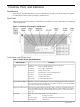
1 Controls, Ports, and Indicators Introduction This chapter describes the controls, ports, and indicators found on the front panel, rear panel, and internal locations of the hp Integrity cx2600 Server. Front Panel The front panel of the hp Integrity cx2600 Server provides the controls and indicators commonly used for operation.
Table 1-1 Switch/Button and LED Definitions (continued) Switch or Button System LED Description Shows the server status as follows: Off Flashing amber at 1 Hz rate Operating power is not available to the server. Attention required. Check the diagnostic LEDs and the MP Status log for information. The LEDs turn off when you access the MP log. NOTE: Input power must be maintained to both power supplies (even those that have failed) for LEDs to display accurate system faults.
Figure 1-2 Hot-Swap Disk Drive LED Indicators Table 1-2 lists the disk drive LED definitions. Table 1-2 Hot-Swap Disk Drive LED Definitions LED Color Description Activity LED Flashing green Status LED Green Amber Drive or slot normal (drive present). Drive fault. Yellow Blank Missing MP card or missing jumper cable. For all HDD on SCSI bus A or B. Pass through mode. Drive access under hard drive control. DVD/DVD-R/DVD-RW Drives The server is delivered with one DVD-ROM drive.
Figure 1-4 HP Integrity cx2620 Server Rear Panel 1 2 3 4 5 6 LVD/SE SCSI Port Management Processor LAN (10/100 LAN) Port and LEDs Gigabit Ethernet LAN A (10/100/1000 LAN) Port and LEDs MP VGA Port MP Reset Button Locator Button and LED 7 8 9 10 11 12 RS-232 MP Serial Console Port (console, remote, UPS) USB Port Serial Port A (Console) Serial Port B System Management LAN B (10/100/1000 LAN) Port and LEDs TOC Button 13 14 15 16 17 18 Keyboard USB Port Mouse USB Port DC Power Supply Wire DC Power Sup
Power Supply Status LEDs A power supply unit has three status LEDs located on the back of the power supply. Consolidated status of two power supplies is reported by the front control panel by the power status LED. The LEDs are described in Table 1-5. Figure 1-5 Rear View of DC Power Supply Table 1-5 lists and describes the power supply status LEDs. Table 1-5 Power Supply Status LEDs LED Color State Status DC In Green On DC power (-40 to -72 VDC) is available to the power supply.
Table 1-6 Gigabit 10/100/1000 base-T Ethernet LAN A Status LEDs LED 1. Gbit 2. 100 Mbit 3. Link 4. Activity Location Color State Status Top Green Off On No 1000 Mbps link has been detected. Port is linked at 1000 Mbps. 2nd from top Green Off On No 100 Mbps link has been detected. Port is linked at 100 Mbps. 2nd from bottom Green Off On No 10 Mbps link has been detected. Port is linked at 10 Mbps. Bottom Green Off On No LAN activity has been detected.
Figure 1-7 System Board LEDs Table 1-8 lists the system board LEDs. Table 1-8 System Board LEDs LED Description Standby (STBY) The standby LED displays the power status of the server. It is lit when power is applied (DC In LED on either power supply is lit). If power is applied and this indicator is off, you may have to replace the system board. BMC The baseboard management controller (BMC) heartbeat LED flashes whenever the BMC is active.
Figure 1-8 LEDs on Management Processor Board Table 1-9 lists the MP card LEDs. Table 1-9 Management Processor Board LEDs LED 16 Description DS1 This fault indicator flashes when an MP fault is detected. DS2 The MP heartbeat indicator flashes when the MP is active.
2 External Connectors Connector Pinouts The following ports and connectors are found on the rear panel of the hp Integrity cx2600 Server.
Table 2-1 USB Port Connector Pinouts Pin Number Signal Description 1 +5VDC 2 MR 3 PR 4 Ground Serial Ports Figure 2-3 Serial Port Connector Table 2-2 RS-232 Serial Console Port Pinouts Pin Number Signal Description 1 Data carrier detect 2 Receive data 3 Transmit data 4 Data Term ready 5 Ground 6 Ring indicator 7 Clear to send 8 Request to send 9 Data set ready System Management LAN Port Figure 2-4 System Management LAN Port Table 2-3 System Management LAN Port Pinouts Pin Num
Table 2-3 System Management LAN Port Pinouts (continued) Pin Number Signal Description 4 Not used 5 Not used 6 RXN 7 Not used 8 Not used Management Processor VGA Port Figure 2-5 MP VGA Port Table 2-4 MP VGA Port Pinouts Pin Number Signal Description Pin Number Signal Description 1 Red 9 +5 VDC 2 Green 10 Sync return (ground) 3 Blue/RXP 11 Not used 4 Not used 12 Monitor ID bit 1 5 Video self test (ground) 13 Horizontal sync (+) 6 Red return (ground) 14 Vertical sync (–
Table 2-5 Gigabit LAN Port Pinouts (continued) Pin Number Signal Description 7 Not used 8 Not used Table 2-6 MP LAN Port Pinouts Pin Number Signal Description 1 TXP 2 TXN 3 RXP 4 Not used 5 Not used 6 RXN 7 Not used 8 Not used SCSI Port, Ultra 3, 68-Pin Two Ultra 3, 68-pin SCSI connectors are located on the host bus adapter (HBA) located in PCI slot 1. The upper connector supports SCSI channel A and the lower connector supports SCSI channel B.
Table 2-7 SCSI Port Pinouts (continued) Pin Number Signal Description Pin Number Signal Description 14 S14 (+DB P) 48 S48 (–DB P) 15 S15 (GND) 49 S49 (GND) 16 S16 (DIFFSENS) 50 S50 (GND) 17 S17 (TERMPWR) 51 S51 (TERMPWR) 18 S18 (TERMPWR) 52 S52 (TERMPWR) 19 S19 (RESERVED) 53 S53 (RESERVED) 20 S20 (GND) 54 S54 (GND) 21 S21 (+ATN) 55 S55 (–ATN) 22 S22 (GND) 56 S56 (GND) 23 S23 (+BSY) 57 S57 (–BSY) 24 S24 (+ACK) 58 S58 (–ACK) 25 S25 (+RST) 59 S59 (–RST) 26 S
3 Installing Additional Components Safety Information This chapter describes installing additional or optional hardware to your hp Integrity cx2600 Server. Follow the procedures listed below to ensure safe handilng of components and to prevent harm to both you and the HP Server: • Use an antistatic wrist strap and a grounding mat, such as those included in the Electrically Conductive Field Service Grounding Kit (HP 9300-1609). • Handle accessory boards and components by the edges only.
5. in place. If the server is tray-mounted, it is not held in the rack and can fall from its mounting. Do not extend the server from the rack, remove it from the rack for internal access. Remove the top cover. See “Removing the Top Cover” (page 29). Removing the Server From a Rack WARNING! Do not attempt to lift the server alone. The server can weigh as much as 32 kilograms (70 lbs.). Serious injury may result if this warning is not observed. NOTE: Ensure there is enough area (approximately 1.
Install the Server into a Rack WARNING! Do not attempt to lift the server alone. The server can weigh as much as 32 kilograms (70 lbs.). Serious injury may result if this warning is not observed. To insert the server into the rack, follow these steps: 1. Engage the server slides or mounting kit, as appropriate. 2. Slide the server inward and push the server into the rack until it is in position. 3. Connect server cables to rear panel connectors. 4.
NOTE: The filler assemblies are removed and installed in the same manner as described for hard drives. Simply pull the dummy release lever to pull the filler from the server. When inserting a filler, push the filler into position. To remove a hot-plug disk drive, perform the following steps: CAUTION: The disk drives in the server are not hot-swappable: they are merely hot-pluggable. A manual software procedure may be required to safely remove or insert disk drives while the server is running.
4. 5. 6. Press the release lever until it is flush with the front of the server. The release lever clicks as it locks into position. If the operating system was stopped in step Step 1, reset the system to the EFI Boot Maintenance Menu to rescan the hard drives. If the operating system was stopped in step Step 1, use the EFI Shell map command to verify that you correctly installed the newly inserted drive.
1. 2. 3. 4. If rack-mounted, you may need to extend a slide-mounted server out from the rack for better access. If necessary, slide the server out to the fully extended position. Remove power from the power supply being replaced. Disconnect power at the DC source end of the power cable, using the disconnect device that is part of the rack or facility power system. Loosen the two knurled knobs on the power-supply cable clamp to release the power feed leads.
13. Install the terminal barrier strip cover (removed in step 11). Hang the cover on the upper tabs and snap the cover into place. 14. Route the power cable through the power supply cable clamp and tighten the two knurled knobs to secure the cable in place. 15. Connect the power cable to the DC power source.
Removing the Top Cover To remove the top cover, follow these steps: WARNING! Hazardous voltages are present within the server when power is applied. Do not remove the server top cover without first turning off and disconnecting power. Always replace the top cover before turning the system on. 1. 2. 3. 4. Power off and disconnect system power. Disconnect power at the DC source end of the power cables, using the disconnect device that is part of the rack or facility power system.
5. Slide the cover toward the rear of the server chassis and lift it straight up. Installing the Top Cover To install the top cover, follow these steps: 1. Align each pair of tabs on the left and right sides of the cover with the corresponding slots in the chassis. Set the cover in place on the chassis. 2. Align the three tabs on the front of the cover with the corresponding apertures at the top front of the chassis and insert the tabs into the slots. 3.
less than 30 seconds eliminates the requirement for a system reboot. Hot-swapping a fan in less than two minutes enables continued operation and prevents automatic shutdown. CAUTION: Operating the server with the front grill removed risks EMI. Operate the server with the front grill removed only when hot-swapping a fan. Always replace the front grill immediately after replacing a fan. Observe all ESD safety precautions while performing this procedure.
To remove and install a hot-swappable fan from the front of the server chassis, follow these steps: CAUTION: Hot-swapping a fan can interrupt system operation. If you are hot-swapping a fan assembly in response to an error message, and the system is operating normally, hot-swapping the fan in less than 30 seconds eliminates the requirement for a system reboot. Hot-swapping the fan in less than two minutes enables continued operation and prevents automatic shutdown. 1. 2. 3. 4. 5.
Removing and Installing a Rear Panel Hot-Swappable Fan Figure 3-8 Removing a Rear Panel Hot-Swap Fan To remove and install the hot-swap fan from the rear of the server chassis, follow these steps: NOTE: 1. The server does not need to be removed from the rack for fan replacement. Use the ACX-15 Torx screwdriver to loosen the two captive mounting screws that secure the fan unit to the server chassis (Figure 3-8). CAUTION: Hot-swapping a fan can interrupt system operation.
4. Tighten the two captive screws that secure the fan unit to the server chassis. PCI Card Installation The hp Integrity cx2600 Server has four 64-bit, 133 MHz PCI-X accessory card sockets located in a removable card cage. You must remove the PCI card cage before you can remove or install PCI cards. The following sections describes how to remove and open the card cage, install PCI cards, and reinstall the PCI card cage.
6. 7. 8. Place the card cage on an ESD-protected work surface. Orient the card cage such that PCI card connectors (within the card cage) are at the bottom, when viewed through the open side of the card cage, and cards can be removed by lifting them from the sockets. Remove the cover that is now on top of the card cage by sliding the cover toward the rear of the card cage and lifting the cover. Remove the cover from the card cage.
6. If there are any empty sockets in the card cage, install a blank panel in the bulkhead opening at the end of the card cage. The blank panel is necessary to ensure correct airflow when the card cage is installed in a working server. Installing a PCI Card NOTE: You must remove the PCI card cage from the server chassis to enable installation of PCI cards. The four connectors in the PCI card cage are identical and have the same capabilities. You can install a compatible PCI card in any slot.
Figure 3-11 Installing the PCI-X Card Cage 3. 4. 5. 6. Press the release lever down into position to lock the card cage into place in the chassis. Install the chassis top cover. See “Installing the Top Cover” (page 30). Reconnect rear panel cables, and turn on the system. To verify that you have correctly installed the PCI-X card, run the info io command at the EFI Shell. Installing Processors This section provides information about installing processors and memory.
Figure 3-12 Processors in Server Chassis (Top Cover Removed) Removing a Processor To remove a processor, proceed as follows: 1. If rack-mounted, extend the server out from the rack until it stops. See “Accessing a Rack-Mounted Server” (page 22). WARNING! Ensure the system is powered down and all power sources have been disconnected from the server prior to removing or replacing components. Voltages are present at various locations within the server whenever a DC power source is connected.
Figure 3-13 Disconnect Power Module Cable 7. Unscrew the power module non-captive mounting screws and disconnect the module from its processor by sliding it toward the back of the chassis. Figure 3-14 Unscrew Power Module Mounting Screws 8. Slide the power module toward the rear of the system board disconnecting the power module from the processor module.
Figure 3-15 Disconnect Power Module from Processor Module 9. Life the power module up and out of the chassis. Place the power module into an anti-static container. Figure 3-16 Remove Power Module 10. Disconnect the processor module turbo fan power cable.
Figure 3-17 Disconnecting the Turbo Fan Cable 11. Release the four heatsink captive screws using the special processor tool. Figure 3-18 Releasing Heatsink Captive Screws 12. Slide the sequencing retainer plate toward the back of the chassis to open the hole in the edge of the turbo fan heatsink for insertion of the special processor tool into the processor locking mechanism.
Figure 3-19 Sliding the Sequencing Retainer Plate 13. Unlock the processor-locking mechanism using the Allen side of the IFP-CPU tool. Insert the Allen side (hex) of the IPF-CPU tool into the lock access hole that runs down through the edge of the turbo fan heatsink.
IPF-CPU tool counterclockwise 180 degrees. Verify that the processor-locking mechanism is rotated into the unlocked position. CAUTION: The zero insertion force (ZIF) socket for the processor is locked and unlocked by half of a full turn of the IPF-CPU tool. The counterclockwise 180 degree rotation (half turn) unlocks the socket. A clockwise 180 degree rotation locks the socket. Attempting to turn the locking mechanism more than 180 degrees can severely damage the socket.
Figure 3-21 Lift Processor Module and Turbo Fan Straight Up 15. Place the turbo fan heatsink upside down to ensure the pins do not get bent. Installing a Processor The following procedure is applicable to installation of processor 0 or processor 1. You must install processor 0 before installing processor 1. NOTE: Installation instructions are provided with replacement processors. Read those instructions carefully.
5. Remove the chassis top cover. See “Removing the Top Cover” (page 29). CAUTION: Observe all ESD safety precautions while performing processor installation. Failure to follow ESD safety precautions can result in damage to the server. 6. 7. Remove the processor airflow guide by lifting it up and out of the server. Ensure that the processor locking mechanism is rotated to the unlocked position (Figure 3-22). Figure 3-22 Processor Locking Mechanism 8. 9. Inspect the pins of the processor to be installed.
CAUTION: Do not press the processor module into the socket. When properly aligned, the processor pins seat into the socket by themselves. No additional pressure is required. You can damage the pins if you apply pressure. Figure 3-23 Aligning the Processor Power Module 11. Use the Allen side of the IPF-CPU tool to lock the processor in place on the system board.
Figure 3-24 Securing Heatsink Captive Screws 14. Connect the power cable for the processor turbo fan to its connector on the system board. 15. Slide the CPU power module on the system board metal mounting bracket so that the power module connector aligns with the connector on the processor.
16. Align the two mounting screw holes on the power module with their screw holes on the system board metal mounting bracket. Screw in the power module mounting screws (M3 x 23mm long pan T15 crest cup stainless steel, two per CPU). Figure 3-26 Installing the Power Module Mounting Screws 17. Connect the processor module turbo fan power cable to the connector on the system board. Figure 3-27 Connect the Turbo Fan Cable 18. Connect the CPU power module power cable to the connector on the system board.
Figure 3-28 Connect the Power Module Cable 19. 20. 21. 22. 23. 24. Place the processor airflow guide in position. Install the chassis top cover. See “Installing the Top Cover” (page 30). If necessary, reinstall the chassis in the rack. See “Install the Server into a Rack” (page 24). Reconnect power and system cables to rear panel connectors. Turn on the system. Run the info cpu command at the EFI Shell prompt to verify that the processor has been installed correctly.
1. If rack-mounted, extend the server out from the rack until it stops. See “Installing Components When the Server Is in a Rack” (page 114). 2. Power off the server. Disconnect all external cables. 3. Remove the server from the rack and place it on an ESD-protected work surface. See “Removing the Server From a Rack” (page 115). 4. Remove the top cover from the chassis. See “Removing and Replacing the Top Cover” (page 123). 5. Remove the memory airflow guide.
5. Remove the top cover from the chassis. See “Installing the Front Grill and Top Cover” (page 28). CAUTION: Observe all ESD safety precautions while performing DIMM installation. Failure to follow ESD safety precautions can result in damage to the server. 6. 7. Remove the memory airflow guide. Locate the DIMM sockets where you will install the DIMMs (Figure 3-29). Figure 3-29 DIMM Slots 8.
Figure 3-30 Inserting a DIMM into a DIMM Socket 10. Snap the socket retainer clips into place, ensuring that the DIMM is locked into the socket. 11. Repeat steps 7 through 10 for each DIMM to be installed. 12. Set the memory airflow guide in position and reinstall the top cover.
4 Troubleshooting Introduction This chapter presents troubleshooting information. Basic tips for startup problems are presented, audio cues and LED indicators are described and interpreted, are error messages (and how to retrieve them) are described. In addition, problems that are associated with I/O paths and functions are discussed here. Troubleshooting Methodology WARNING! Always disconnect the power cords and unplug telephone cables before removing the server cover.
If the server is off, and power is connected to server power supplies, the front panel power LED blinks at a 1 Hz rate. In this state, standby power is available to server circuits, but main power is off. Pressing and holding the Power button accomplishes the following: • 1 – 3 seconds: System power turns on. • 3 - 5 seconds. The e-buzzer will repeat the last stored error message (beep code).
Operating System Boots with Problems If the operating system is running, you are experiencing problems, use the following tools to help solve the problem: • Beep Codes • LEDs • Error Messages and event logs Intermittent Server Problems You can usually trace intermittent problems that occur during installation to power source problems, a loose connector, or some other hardware problem. If you are experiencing intermittent problems, follow these steps: 1. Check MP logs and analyze the problem.
different number of beeps for each type of error. If you do not hear the beeps, or may have miscounted beeps, you can repeat the message by pressing the front panel power button for 3 to 5 seconds. (Release the power button when you first hear the e-buzzer. Do not press the power button for more than 5 seconds.) The e-buzzer emits a modem-like sound that is repeated three times. Next, the e-buzzer emits a beep code consisting of 0 to 7 beeps occurring at 1 second intervals. Each beep lasts 1 second.
NOTE: If input power is not maintained to both power supplies on HP Integrity cx2600 and cx2620 servers, front panel LEDs might not display accurate system information. Input power must be maintained to both power supplies (even those that have failed) for LEDs to display accurate system faults. Removing input power is not equivalent to a power supply failure as detected by the circuitry which drives the front panel LED status.
Table 4-2 Front Panel LED Definitions (continued) LED/Button System State Diagnostic LEDs (1 thru 4) Flash Rate Color Description None Yellow or Red Displays system error condition (when system LED is flashing yellow) or fault condition (when system LED is flashing red). For error code information, see Table 4-3 . The system is off (no power to LAN circuits) or hardware failure. LAN LED Off None N/A LAN LED Active Steady Green LAN link is established but LAN is inactive.
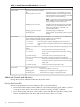
Table 4-3 Diagnostic LED Displays and Descriptions (continued) Diag 1 LED Diag 2 LED Diag 3 LED Diag 4 LED System LED Description Green Green Off Red Flashing Yellow Fan 4 warning. BMC is reporting that one fan rotor is turning more slowly than expected or is stopped. Investigate problem at the first opportunity. Green Green Red Off Flashing Yellow System battery voltage low. Replace the system battery. Green Red Off Red Flashing Yellow Power supply 1 warning.
Table 4-3 Diagnostic LED Displays and Descriptions (continued) Diag 1 LED Diag 2 LED Diag 3 LED Diag 4 LED System LED Description Green Red Off Red Flashing Red Power supply 1 fault. Replace power supply 1, the power supply interface assembly, or the system board. Green Red Green Red Flashing Red 12V range error. Something is loading the 12V source. This can be the power supply, the power supply interface, the system board, or any used circuit.
Figure 4-2 Rear Panel LEDs 1 2 3 4 MP LAN LEDs Gigabit LAN LEDs System Management LAN (10/100) LEDs Locator Button LEDs 5 6 7 Power Supply Fault LED Power Supply DC Out LED Power Supply DC In LED 8 9 10 Power Supply Fault LED Power Supply DC Out LED Power Supply DC In LED Table 4-4 Rear Panel LED Definitions LED/Button Color Description MP Self Test LED (top) Green When off, self test is not active. When lit, the MP is running self test.
Table 4-4 Rear Panel LED Definitions (continued) LED/Button Color Description Power Supply Fault Amber Lit when a power supply failure is detected. Indicates that power supply has been cycled down or is not fully functional. Power Supply DC Out Green Lit when a power supply is operating normally. Indicates that DC power is being supplied to server circuits. Power Supply DC In Green Lit when power (-36 to -72 VDC) is supplied to the power supply. Indicates that source power is available.
Table 4-5 EFI Error and Warning Messages (continued) Error Number Message Description/Solution 19 Error writing BMC token on download Communication with the BMC failed. Replace the system board. 20 Non-volatile Memory (NVM) token access error Communication with the BMC failed. Replace the system board. 21 BMC token write error during NVM write through Communication with the BMC failed. Replace the system board. 22 Error reading BMC token on upload to NVM Communication with the BMC failed.
Table 4-5 EFI Error and Warning Messages (continued) Error Number Message Description/Solution 43 At least one (1) CPU is overclocked Check processor installation and match CPU part numbers. CPUs must be identical. 44 Monarch changed to lowest stepping CPU Check processor installation and match CPU part numbers. CPUs must be identical. 46 CPUs loaded in wrong order Reload processors in the correct order. 48 SAL NVM cleared Information only, no action required.
• • • 5. Previous boot Live events Clear SEL/FPL logs Select the desired log for viewing. (For additional information about the management processor and all commands refer to “Utilities” (page 73)) SEL and FPL Log Entries This section is a quick reference for the IPMI events recorded in the SEL and FPL files. These logs are available via the MP card interface or the BMC CLI. • All entries from the SEL are forwarded to the FPL. The FPL is a circular log so the newest entries replace the oldest.
Accessing the Logs with MP Commands The SEL and FPL data can also be accessed from the MP logs using the MP card SL command. The SDM (set display mode) command determines the format of the display: • raw hex mode. • text mode. • keyword mode.
Table 4-7 I/O Card Slot Paths I/O Slot Path Rope MHz Slot 1 Acpi(HWP0002,400)/Pci(1|0) 4, 5 133 Slot 2 Acpi(HWP0002,300)/Pci(1|0) 3 133 Slot 3 Acpi(HWP0002,200)/Pci(1|0) 2 133 Slot 4 Acpi(HWP0002,600)/Pci(1|0) 6 133 Note: Rope 7 is used to access optional ECI at 33 MHz. Troubleshooting Using Offline Support Tools You can use offline support tools to troubleshoot the server.
Figure 4-3 Offline Diagnostic Main Menu *************************************************************************** ****** ****** ****** Offline Diagnostic Environment ****** ****** ****** ****** (C) Copyright Hewlett-Packard Co 1993-2003 ****** ****** All Rights Reserved ****** ****** ****** ****** HP shall not be liable for any damages resulting from the ****** ****** use of this program. ****** ****** ****** ****** TC Version B.00.10 ****** ****** SysLib Version B.00.06 ****** ****** Mapfile Version B.
NOTE: Remove the server top cover during this procedure, so you can observe the system board LEDs and install assemblies. With the top cover removed, the system powers off after two minutes of operation. After installing an assembly, apply power and immediately check for status and symptoms. Use the MP to access error messages after the system has powered off. To build up the system, follow these steps: 1.
Table 4-8 Interpret Diagnostic and System LEDs Diag 1 LED Diag 2 LED Diag 3 LED Diag 4 LED System LED Description Off Red Off Off Flashing Red The BMC is reporting a level 7 error due to the missing server component. Continue with the build up procedure. Any Other LED Status Display 6. 7. 8. Replace the system board. For additional information, see Table 4-3 (page 58). Power off the server and disconnect power. (If the system has shut itself down, only disconnect power.
Table 4-10 Interpret Diagnostic and System LEDs (continued) Diag 1 LED Diag 2 LED Diag 3 LED Diag 4 LED System LED Description Red Off Off Green Flashing Red The BMC is reporting a fatal error due to missing DIMMs. Continue with the build up procedure. Any Other LED Status Display Replace the MP card or the system board. For additional information, see Table 4-3 (page 58) . 12. Power off and disconnect power from the server. (If the system has shut itself down, only disconnect power.
When the system powers on, it pauses at the Boot Option screen. Select one of the following options: • EFI Shell (built in). A command line interface that enables you to operate EFI commands or create and run automounted scripts. • EFI Boot Option Maintenance Menu enables you to select the order of the devices from which you want the firmware to boot the OS. You can also configure the system to boot from a configuration file.
5 Utilities This appendix describes the utilities that are part of the server. These include the EFI Boot Manager, and EFI-POSSE. Extensible Firmware Interface Boot Manager Extensible Firmware Interface (EFI) is an OS and platform-independent boot and pre-boot interface. EFI resides between the OS and platform firmware. This enables the OS to boot without having details about the underlying hardware and firmware.
different ways to bring up the system. For example, you can boot to the EFI Shell, to an operating system located on the network or residing on media in the server, or the EFI Boot Maintenance menu. The following options are available in the EFI Boot Manager menu Boot from a File Automatically adds EFI applications as boot options or enables you to boot from a specific file. When you select this option, the system searches for an EFI directory.
Table 5-1 EFI Commands (continued) EFI Shell Command BCH Command Equivalent (PA-RISC) BCH Command Parameters (PA-RISC) [
Table 5-1 EFI Commands (continued) EFI Shell Command BCH Command Equivalent (PA-RISC) BCH Command Parameters (PA-RISC) Definition info io IO Display firmware version for PDC, ICM, and complex lanaddress LanAddress Display core LAN station address info mem Memory Display memory information info cpu PRocessor Display processor information errdump clear CLEARPIM Clear (zero) the contents of PIM mm MemRead pdt page deallocation table (pdt) Display or clear the page deallocation table err
by a menu name for more information on that menu. If you issue help within the bch option and a menu name, it displays a list of commands that appear under that BCH menu. You can then issue help followed by bch, the menu name, and a BCH command name to display information about that command. This points you to the EFI command that has taken the place of that BCH functionality, or will inform the user that the functionality no longer exists.
Example 5-1 help Command Shell> help List of classes of commands: boot -- Booting options and disk-related commands configuration -- Changing and retrieving system information devices -- Getting device, driver and handle information memory -- Memory related commands shell -- Basic shell navigation and customization scripts -- EFI shell-script commandsType "help" followed by a class name for a list of commands in that class Type "help" followed by command name for full documentation Example 5-2 help bch Com
Example 5-4 help cpuconfig Command Shell> help cpuconfig Deconfigure or reconfigure cpus CPUCONFIG [module] | [threads] [on|off] module : Specifies which cpu module to configure threads : Use to display info or configure threads on|off : Specifies to configure or deconfigure a cpu module or threads Note: 1. Cpu status will not change until next boot. 2. Specifying a cpu number without a state will display configuration status.
Example 5-5 help ioconfigCommand Shell> help ioconfig Deconfigure or reconfigure IO components or settings IOCONFIG [fast_init|wol [on|off]] fast_init wol on|off Specifies device connection policy setting Specifies System Wake-On-LAN setting Specifies to configure or deconfigure a feature or component Note: 1. If fast_init is enabled, firmware will connect only the minimum set of devices during boot. This feature might cause boot failure; disable this feature if failure occurs. 2.
Table 5-2 Communications Parameters Parameter Value RECEIVE_FIFO_DEPTH 1 TIMEOUT 1000000 PARITY No parity DATA_BITS 8 STOP_BITS 1 CONTROL_MASK 0 boottest Interacts with the speedy boot variable enabling it to be set appropriately.
Example 5-6 boottest Command Shell> boottest BOOTTEST Settings Default Variable Selftest Setting ------------------------------------booting_valid On (OS speedy boot aware) early_cpu Run this test late_cpu Run this test platform Run this test chipset Run this test io_hw Run this test mem_init Run this test mem_test Run this test Example 5-7 boottest early_cpu off Command Shell> boottest early_cpu off BOOTTEST Settings Default Variable Selftest Setting ------------------------------------booting_valid On (O
NOTE: The last remaining configured CPU in a server cannot be deconfigured. Example 5-8 cpuconfig Command Shell> cpuconfig PROCESSOR INFORMATION CPU --0 1 Speed ------1.6Ghz 1.6Ghz Proc Rev --------B1 B1 Model ------0 0 Family ----31 31 Arch Processor Rev State ------ ----0 Sched Deconf 0 Active default Enables you to restore non-volatile memory (NVM) to default values and clear NVM storage values.
Parameters target: all cpu cache mem io boot chiprev fw sys warning 84 Utilities valid targets are: display everything display information on cpus display information on cache display information on memory display information on io display boot-related information display information on chip revisions display firmware version information display system information display warning and stop boot information
Example 5-9 info all Command Shell> info all SYSTEM INFORMATION Date/Time: Sep 24, 2004 17:27:17 (20:04:09:24:17:27:17) Manufacturer: hp Product Name: server cx2620 Product Number: AB333A Serial Number: USR0418201 UUID: 336B81EE-A9AF-11D8-9653-3F6E1533CC31 System Bus Frequency: 200 MHz PROCESSOR MODULE INFORMATION # of L3 L4 Family/ CPU Logical Cache Cache Model Module CPUs Speed Size Size (hex.) Rev ------ ------- -------- ------ ------ ------- --0 1 1.
Logical ------0/0 Logical --------0/0 Warnings -------- AutoBoot: ON - Timeout is : 10 sec Boottest: BOOTTEST Settings Default Variable OS is not speedy boot aware.
System Wake-On-LAN: Enabled BOOT INFORMATION Monarch CPU: Current Monarch CPU Module/ Logical ------0/0 Preferred Monarch CPU Module/ Logical --------0/0 Warnings -------- AutoBoot: ON - Timeout is : 10 sec Boottest: BOOTTEST Settings Default Variable OS is not speedy boot aware.
Root Bridge Host Bridge Host Bridge Host Bridge Host Bridge Host Bridge Host Bridge Host Bridge Other Bridge Other Bridge Baseboard MC 0 0000 0001 0002 0003 0004 0006 0007 0 0 0 1229 122e 122e 122e 122e 122e 122e 122e 0 0 0 0023 0032 0032 0032 0032 0032 0032 0032 0002 0009 0342 Example 5-10 info cpu Command This example has processor hyperthreading turned on: Shell> info cpu PROCESSOR MODULE INFORMATION CPU Module -----0 1 # of Logical CPUs ------4 4 Speed -------1.4 GHz 1.
Example 5-11 info mem Command Shell> info mem MEMORY INFORMATION --0 1 2 3 4 5 ---- DIMM A ----DIMM Current ------ ---------256MB Active 256MB Active ------------- ---- DIMM B ----DIMM Current ------ ---------256MB Active 256MB Active ------------- Active Memory : 1024 MB Installed Memory : 1024 MB Example 5-12 info io Command Shell> info io I/O INFORMATION BOOTABLE DEVICES Order ----1 Media Type ---------CDROM Seg Bus Dev Fnc # # # # --- --- --- --00 00 01 00 00 00 01 01 00 00 01 02 00 00 02 00 00 2
Example 5-13 info boot Command Shell> info boot BOOT INFORMATION Monarch CPU: Current Monarch CPU Module/ Logical ------0/0 Preferred Monarch CPU Module/ Logical --------0/0 Warnings -------- AutoBoot: ON - Timeout is : 10 sec Boottest: BOOTTEST Settings Default Variable OS is not speedy boot aware.
Example 5-14 lanaddress Command LAN Address Information: LAN Address Path ----------------- ---------------------------------------Mac(00306E4C4F1A) Acpi(HWP0002,0)/Pci(3|0)/Mac(00306E4C4F1A)) *Mac(00306E4C0FF2) Acpi(HWP0002,100)/Pci(2|0)/Mac(00306E4C0FF2)) monarch Displays or modifies the ID of the bootstrap processor. The preferred monarch number is stored in NVM.
Operation With no options specified, the command displays the PDT information for the server. The PDT is cleared and a reboot is required for memory reallocation and safe booting.
Example 5-18 sysmode Command Shell> sysmode System Mode: NORMAL Shell> sysmode admin You are now in admin mode. Shell> sysmode service You are now in service mode.
1. At the EFI Shell prompt, enter the info io command to map the parameters for all PCI cards installed in the server. A list of all the devices that are installed in the server and managed by EFI drivers displays.
The vendor (0x1000) and device (0x0030) are the IDs for a SCSI interface. Of the devices with those IDs, this device has two channels (Fnc # of 00 immediately followed by Fnc # of 01). Also, this SCSI interface has a non-numeric (XX) slot # indicating that it is on the system board. 2. From the EFI Shell prompt, enter the devtree command to obtain the controller’s handle for the SCSI interface. A tree of all EFI-capable devices installed in the system displays.
Drv[3F] Ctrl[19] Lang[eng] Drv[45] Ctrl[1C] Lang[eng] Drv[45] Ctrl[1D] Lang[eng] This listing shows which driver controls which device (controller). This information describes a SCSI interface because the values shown for Ctrl—17 and 18—are the controller’s handles for the SCSI interface two channels (from the information displayed by the devtree command). NOTE: The EFI driver’s handle values change on every boot.
PCI-X Bus, PCI-X Device, and PCI-X Function to the Bus #, Dev #, and Fnc # values from the info io command. CAUTION: Do not change the value for any of the following fields on the Adapter Properties screen: • Auto Termination • SCSI Parity • SCSI Bus Scan Order • Spinup Delay (Secs) Changing any of these fields can cause unpredictable results.
15. At the EFI Shell prompt, enter the Shell> reset command. The system starts to reboot. This is required to cause the new SCSI setting. Management Processor The management processor is an independent support system for the server. It provides a way for you to connect to a server and perform administration or monitoring tasks for the server hardware.
MP Welcome Screen MP Welcome screen commands: MP Login: Admin MP password: ***** Hewlett-Packard Management Processor (C) Copyright Hewlett-Packard Company 1999-2003. All rights reserved System Name: xxxxxxxxx MP MAIN MENU: CO: Console VFP:Virtual Front Panel CM: Command Menu CL: Console Log SL: Show Event Logs HE: Main Help Menu X: Exit Connection MP MP commands are described in the following paragraphs.
Table 5-3 (continued) Command Description PG Paging parameter setup PS Power management module status RB Reset BMC RS Reset system through RST signal SA Set access SE Enter OS session SL Show event logs SO Security options SS System processor status SYSREV Current system firmware revisions TC Reset via transfer of control (TOC) TE Tell- send a message to other users UC User configuration VFP Virtual front panel WHO Display connected management processor users X Exit manageme
• • TRANSMIT CONFIGURATION STRINGS: Disable this setting whenever the modem being used is not compatible with the supported modem (MT5634ZBA). MODEM PRESENCE: When the modem may not always be connected, set this parameter to “not always connected.” For example: A modem attached through a switch. In mode “not always connected,” no dial-out functions are allowed: DIAL-BACK is disabled, and PAGING is not possible. The MP mirrors the system console to the MP local, remote/modem, and LAN ports.
This command allows the local or remote port user to connect over the MP LAN to another MP on the network. The user that launches the command is given a private connection to the other MP over the LAN. To return to the original MP, type CTRL+] to disconnect the CSP session. Date DATE: Displays the current date, as generated in the MP real-time clock.
mode, this command displays a list of command interface commands available to the user. It also displays detailed help information in response to a topic or command at the help prompt. Display System ID ID: Display/modify system information This command allows the user to display and modify the following: • SNMP contact information • SNMP server information • SPU hostname Inactivity Timeout IT: Inactivity Timeout settings The session inactivity timeout is up to 1,440 minutes—default is 60 minutes.
Modem Reset MR: Modem Reset This command makes the MP send an AT Z command to the modem, which resets it. Any modem connections are lost. The initialization results can be viewed via the MS command. Modem Status MS: Modem Status—display modem status The MS command displays the state of the modem lines connected to the remote/modem serial port. The display can be updated by pressing Enter.
Set Access SA: Set access options—configures access for LAN and remote/modem ports This command will disconnect modem, LAN, and web users if access is disabled. Create Local Session SE: Log into the system on local or remote port Only valid from the local or remote/modem port, SE allows the user to leave the MP command interface and enter a system session. Other mirrored MP users are placed in console mode. The session user returns to the mirrored MP session on exit.
Table 5-4 Alert Levels Severity Definition 0 Minor forward progress 1 Major forward progress 2 Informational 3 Warning 5 Critical 7 Fatal Security Options SO: Configure security options and access control (users, passwords, and so on) This command modifies the security parameters of the MP, which include login timeouts and allowed password faults. If configured, when you access the MP via the modem port, the MP hangs up and dials the user back.
Virtual Front Panel VFP: Display Virtual Front Panel This command is executed from the Main Menu. The VFP display is a summary of the current state of the system, including current LED states. When invoked, the VFP command presents a summary of system status, using direct console addressing. If the terminal is not recognized by the MP, VFP mode will be rejected. The summary is sent to each individual user to avoid issues related to terminal type and screen display mode.
Booting the Server To boot the server, press the power switch located on the front panel. If the autoboot function is enabled, the system will boot to the installed operating system. If autoboot is not enabled, the system will enter the EFI boot manager. The EFI boot manager allows you to control the server’s booting environment. For more information about the EFI boot manager, review “Utilities” (page 73).
Configurable Components Drv[23] Ctrl[29] Lang[eng]Shell> drvcfg -c 2a Configurable Components Drv[2A] Ctrl[2C] Lang[eng] 3. Set the enumeration option for the driver 23 and controller 29.
gF7D00000) blkD : Acpi(HWP0002,500)/Pci(2|0)/Fibre(WWN21000020375A5E5B,Lun0) blkE : Acpi(HWP0002,500)/Pci(2|0)/Fibre(WWN21000020375A5E5B,Lun0)/HD(Part1,Si g7D930000) blkF : Acpi(HWP0002,500)/Pci(2|0)/Fibre(WWN21000020375A5E5B,Lun0)/HD(Part2,Si g7D930000) blk10 : Acpi(HWP0002,500)/Pci(2|0)/Fibre(WWN210000203760083D,Lun0) blk11 : Acpi(HWP0002,500)/Pci(2|0)/Fibre(WWN21000020370FC9C0,Lun0) blk12 : Acpi(HWP0002,500)/Pci(2|0)/Fibre(WWN2100002037600863,Lun0) blk13 : Acpi(HWP0002,500)/Pci(2|0)/Fibre(WWN21000020375A
IA64_EFI [Acpi(HWP0002,100)/Pci(1|1)/Scsi(Pun0,Lun0)/HD(Part1,Si IA64_EFI [Acpi(HWP0002,500)/Pci(2|0)/Fibre(WWN21000020375AE714,L IA64_EFI [Acpi(HWP0002,500)/Pci(2|0)/Fibre(WWN21000020375A5E5B,L NO VOLUME LABEL [Acpi(HWP0002,600)/Pci(1|0)/Scsi(Pun4,Lun0)/HD(P Removable Media Boot [Acpi(HWP0002,0)/Pci(3|0)/Ata(Primary,Maste Load File [EFI Shell [Built-in]] Load File [Acpi(HWP0002,100)/Pci(2|0)/Mac(00306E39115D)] Load File [Acpi(HWP0002,200)/Pci(1|0)/Mac(001018042056)] Load File [Acpi(HWP0002,500)/Pci(1|0)/Ma
6 Parts Information This appendix provides the following customer self-repair part information for the HP Integrity cx2620 server. Refer to this appendix whenever ordering parts. • Manufacturing Part Number • Description • Replacement Part Number, if applicable • Exchange Part Number, if applicable Replacement Parts List Part numbers are found by using the part nomenclature from this list to select the correct part from the HP Partsurfer.
Table 6-1 Parts List (continued) Manufacturing Part Number Description Replacement Part Number Exchange Part Number AB216-60001 or AB216-60004 Fan control board AB216-60004 N/A 0957-2089 DC power supply (AB217A) 0957-2089 N/A Fan Assemblies AB216-04008 Front fan assembly AB216-04008 N/A AB216-04002 Rear fan assembly AB216-04002 N/A Miscellaneous Parts A7231-04006 APC / PCI Cage A7231-04006 N/A AB216-04007 PSI PCA AB216-04007 N/A AB216-04012 Baffle, CPU AB216-04012 N/A AB216-0
7 Removing and Replacing Components This chapter provides procedures for removing and replacing components in the server. Safety Information Use care to prevent injury and equipment damage when performing removal and replacement procedures. Voltages can be present within the server. Many assemblies are sensitive to damage by electrostatic discharge.
To install components when the server is in a rack, follow these steps: WARNING! Ensure that the system is powered off and all power sources are disconnected from the server prior to removing or installing server hardware. Voltages are present at various locations within the server whenever a DC power source is connected. This voltage is present even when the main power switch is turned off. Failure to observe this warning can result in personal injury or damage to equipment.
Figure 7-1 Chassis Ground Lug Chassis Ground Lug chasgndlug 5. 6. If the server is slide-mounted, slowly pull the chassis forward (or push from the rear) to extend the chassis from the rack. The server is fully extended when the rail clips are locked in place. Do not extend tray-mounted servers. Tray-mounted servers are not locked in place and can fall if extended from the rack. Disengage the slides or mounting hardware and take the server to a static-free work station.
Removing and Replacing Disk Drives Hot-plug disk drives are located at the front of the server. The following sections remove and reinstall a disk drive. CAUTION: A hot-plug device may require interaction with the operating system before the device can be safely removed from or installed into the server. Determine if the operating system supports replacement of disk drives while the operating system is running.
2. Squeeze inward on the release clip and pull the release lever to pull the drive from the server chassis. Figure 7-3 Disk Drives in Server 2 1 0 S C S I dskdrvfrnt1 Release Clip Release Lever Installing Hot-Plug Disk Drives To install a hot-plug disk drive, follow these steps: 1. If required, (OS does not support hot-plugging) stop the operating system. 2. If a disk filler is installed, remove it by pulling the dummy release lever. 3.
NOTE: A hot-swappable device does not require interaction with the operating system before the device is removed from or installed into the server. If the second power supply is functioning correctly, you can power off and remove a power supply with no effect on server operations. The power to the server (other power supply) does not have to be off to remove or replace a hot-swappable power supply.
Figure 7-5 Removing a Hot-Swappable Power Supply Mounting Screws chaspsxtnd Cable Clamp 1. 2. Handle If rack-mounted, you may need to extend the server out from the rack for better access. If needed, slide the server out to the fully extended position. Disconnect power from the power supply being removed. Disconnect power at the DC source end of the power cable, using the disconnect device that is part of the rack or facility power system.
2. 3. When the power supply is fully inserted into the server chassis, tighten the two mounting screws to secure the power supply in place. Press up on the two lower tabs on the terminal barrier strip cover to snap off the cover. WARNING! Always check that the power cable is not connected to a power source before attempting to connect the power cable to the power supply terminals. Failure to heed this warning can result in injury. 4.
Removing and Replacing the Front Grill Figure 7-7 shows the server with the front grill removed. CAUTION: Operation of the server without the front grill in place makes the server susceptible to electromagnetic interference (EMI) problems, which can result in system failure. Keep the front grill in place during normal operation. Observe all ESD safety precautions while performing this procedure. Failure to follow ESD safety precautions can result in damage to the server.
Removing and Replacing the Top Cover Figure 7-8 shows the server with the top cover removed. CAUTION: Operation of the server without the top cover in place makes the server susceptible to electromagnetic interference (EMI) and overheating problems, which can result in system failure. Keep the top cover in place during normal operation. Observe all ESD safety precautions when removing and replacing the top cover. Failure to follow ESD safety precautions can result in damage to the server.
WARNING! Voltages are present within the server when power is applied. Do not remove the server top cover without first turning off and disconnecting power. Always replace the top cover before turning the system on. 1. 2. 3. 4. 5. Power off and disconnect system power. Disconnect power at the DC source end of the power cables, using the disconnect device that is part of the rack or facility power system. Slide the server out from the rack until it stops.
Figure 7-9 Removing a Front Panel Hot-Swappable Fan Fan 1 Fan 2 Fan 3 Fan 4 chasfan1xtnd Captive Screws 1. 2. 3. Remove the front grill. See “Removing and Replacing the Front Grill” (page 122). Use the ACX-15 Torx screwdriver to loosen the two captive screws on the plastic extractor handle (left side of fan) until they release. Use the extractor handle to pull the fan from the server chassis. NOTE: Hot-swapping a fan can interrupt system operation.
Removing a Rear Panel Hot-Swappable Fan To remove a hot-swappable fan from the rear of the server chassis, follow these steps. Figure 7-10 Removing a Rear Panel Hot-Swappable Fan Mounting Screws Fan 5 chasfan5xtnd 1. 2. 3. 126 If rack-mounted, you may need to extend the server out from the rack for better access. If needed, slide the server out to the fully extended position. Use the ACX-15 Torx screwdriver to loosen the two captive screws that secure the fan unit to the server chassis.
NOTE: Hot-swapping a fan can interrupt system operation. If you are hot-swapping a fan assembly in response to an error message, and the system is operating normally, hot-swapping the fan in less than 30 seconds eliminates the requirement for a system reboot. Hot-swapping the fan in less than two minutes enables continued operation and prevents automatic shutdown. Installing a Rear Panel Hot-Swappable Fan You do not need to remove the server from the rack to replace a fan.
NOTE: Air flows through the server chassis from front to back. Removing the Memory Airflow Guide To remove the memory airflow guide, follow these steps: 1. Power off the server. 2. Remove the top cover. See “Removing and Replacing the Top Cover” (page 123). 3. Grasp the memory airflow guide and lift it from the server chassis. Installing the Memory Airflow Guide To install the memory airflow guide, follow these steps: 1. Reposition cables away from the area where you install the airflow guide. 2.
You may replace these DIMMs, or insert DIMMs into unused quads if desired. When adding DIMMs, you must use a minimum of four like-sized DIMMs in the next available quad. If DIMMs of different sizes are to be installed, the smallest DIMMs (least memory) must be installed in the first quad. DIMMs in the second quad can be equal to or larger (more memory) than the DIMMs in the first quad. If DIMMs are to be installed in the third quad, they must be equal to or larger than the DIMMs in the second quad.
5. 6. 7. Remove the memory airflow guide. See “Removing the Memory Airflow Guide” (page 128). Locate the DIMMs you want to remove (Figure 7-12). Press down on the DIMM socket retainer clips on either end of the DIMM connector until the DIMM ejects from the connector. 8. Lift the DIMM from the system board socket (Figure 7-13). If the removed DIMM is functional, store it for future use. Store DIMMs in static-free containers. 9. Repeat steps Step 6 through Step 8 for each DIMM you want to remove. 10.
Figure 7-13 Inserting a DIMM into a DIMM Socket dimm_sokt NOTE: DIMM connectors are keyed so that you can only install them in the correct orientation. 9. Firmly and evenly push down on each side of the DIMM until it seats in the socket. The socket retainer clips snap up and return to the upright position when the DIMM is fully inserted. 10. Make sure the DIMM is locked in the socket. 11. Repeat steps Step 6 through Step 10 for each DIMM to be installed. 12.
3. Remove the server from the rack and place it on an ESD-protected work surface. See “Removing the Server From a Rack” (page 115). WARNING! Ensure that the system is powered off and all power sources are disconnected from the server prior to removing or installing server hardware. Voltages are present at various locations within the server whenever a DC power source is connected. This voltage is present even when the main power switch is turned off.
NOTE: The four connectors within the PCI card cage are identical and have the same capabilities. You can install a compatible PCI card in any slot. Installing the PCI Card Cage Assembly To install the PCI card cage assembly, follow these steps: WARNING! Ensure that the system is powered off and all power sources are disconnected from the server prior to removing or installing server hardware. Voltages are present at various locations within the server whenever a DC power source is connected.
Figure 7-15 Installing the PCI Card Cage PCI Card Cage Release Lever chaspciccup 4. 5. 6. 7. Press the release lever down to lock the card cage in place in the chassis. Reinstall the chassis cover. See “Removing and Replacing the Top Cover” (page 123). Reinstall the server in the rack and power on the server. See “Inserting the Server Into a Rack” (page 116). Run the info io command at the EFI Shell to verify that you have correctly installed the PCI-X cards.
3. 4. If a cable blocks card removal, or if it is connected to the card, disconnect the cables from the card connectors. Use the ACX-15 Torx screwdriver to remove the retaining screws (M3 x 6mm long pan T15/slot squire cone stainless steel) that secures the card in place (Figure 7-16). Figure 7-16 PCI Card Retaining Screws Card Retaining Screws pciccscrw2 5. 6. Grasp the card by the two opposite edges and lift the card from the socket.
6. 7. Secure the card in the card cage using the retaining screws provided. Connect the cables to the card sockets. Removing and Replacing the LED Status Panel The LED status panel can be removed from the front of the server chassis. It is mounted together with the CD/DVD optical drive assembly. WARNING! Ensure that the system is powered off and all power sources are disconnected from the server prior to removing or installing server hardware.
5. 6. Remove the two noncaptive screws that secure the LED status panel board to the threaded standoffs on the deck, and slide the board forward to disengage the board lock apertures from the keyed standoffs (two each). Remove the board by lifting it off of the deck assembly. Figure 7-18 Removing the LED Status Panel LED Board Mounting Screws chasdvdxtnd LED Board CD/DVD Installing the LED Status Panel CAUTION: Observe all ESD safety precautions while performing this procedure.
Removing and Replacing the CD/DVD Optical Drive You can remove the optical drive from the front of the server chassis. WARNING! Ensure that the system is powered off and all power sources are disconnected from the server prior to removing or installing server hardware. Voltages are present at various locations within the server whenever a DC power source is connected. This voltage is present even when the main power switch is turned off.
components for this procedure is extensive; you must budget adequate time for completion of the steps. A flashlight is not required but can be useful in this effort. WARNING! Ensure that the system is powered off and all power sources are disconnected from the server prior to removing or installing server hardware. Voltages are present at various locations within the server whenever a DC power source is connected. This voltage is present even when the main power switch is turned off.
Figure 7-20 Hard Drive Backplane Mounting Screws Fault DC Out DC In chasfn5out2 Backplane Mounting Screws 12. Slide the backplane board to the right to align locking holes in the unlocked position, and remove the board. Installing the Hard Drive Backplane To install a hard drive backplane, follow these steps: 1. Insert the hard drive backplane through the fan opening in the chassis rear panel. 2.
Removing and Replacing the Power Supply Interface Assembly The power supply interface (PSI) assembly is located under the top cover. You can see the PSI from the rear of the chassis when the two power supply modules are removed. WARNING! Ensure that the system is powered off and all power sources are disconnected from the server prior to removing or installing server hardware. Voltages are present at various locations within the server whenever a DC power source is connected.
8. From the front of the server, locate the two hard drive backplane cables and disconnect them. Figure 7-22 PSI Module From the Front chasnodvdasy CPU Power Pod Interface Cables 9. Remove the PSI assembly, along with the attaching cables, from the server chassis. Installing the PSI Assembly To install a PSI assembly, follow these steps: CAUTION: Observe all ESD safety precautions while performing this procedure. Failure to follow ESD safety precautions can result in damage to the server. 1. 2.
Removing and Replacing the Fan Control Board Remove and replace the fan control board with the server powered off and with the top cover and the front grill removed. This circuit board also provides cable distribution to various elements in the chassis, as it is the termination point for seven different connectors. WARNING! Ensure that the system is powered off and all power sources are disconnected from the server prior to removing or installing server hardware.
Figure 7-23 Fan Control Board Fan Control Board chasfnbrdxtnd 8. Remove the terminating connectors from the cables (Figure 7-24). Figure 7-24 Fan Control Board Connectors P3 Fan Control Board Mounting Screw P11 P4 P8 P1 P5 J1 J2 P12 P2 fncntbrd2 9. Remove the single screw (M3 x .5 10mm long pan T10 crest cup stainless steel) located at the top left corner of the fan control board, which secures the board to the standoffs on which it is mounted. 10.
CAUTION: Observe all ESD safety precautions while performing this procedure. Failure to follow ESD safety precautions can result in damage to the server. 1. 2. 3. 4. 5. 6. Clear a pathway of cables and set the fan control board in place, hooking its locking apertures onto the standoff locks. Slide the board toward the rear of the chassis (Figure 7-23 and Figure 7-24).
Removing the Management Processor Board To remove the MP board, follow these steps: 1. If rack-mounted, extend the server out from the rack until it stops. See “Installing Components When the Server Is in a Rack” (page 114). 2. Power off the server. Disconnect all external cables. 3. Remove the server from the rack and place it on an ESD-protected work surface. See “Removing the Server From a Rack” (page 115). 4. Remove the top cover. See “Removing and Replacing the Top Cover” (page 123). 5.
Replacing the Management Processor Board Battery A keep-alive battery is located on the under-side of the MP board, with a design lifetime of ten years. This 3 volt CR2032 type battery can be accessed for replacement only when the MP board is out of the system. To replace the battery, perform these steps: CAUTION: Observe all ESD safety precautions while performing this procedure. Failure to follow ESD safety precautions can result in damage to the server. 1.
Figure 7-27 Processors in Server Chassis (Top Cover Removed) CPU 0 CPU 1 F R O N T chastop2cpus A tool kit is provided with replacement processors. An IPF CPU tool kit is required for successful completion of these procedures. Removing a Processor WARNING! Ensure the system is powered down and all power sources have been disconnected from the server prior to removing or replacing components. Voltages are present at various locations within the server whenever a DC power source is connected.
Figure 7-28 Disconnect Power Module Cable 7. Unscrew the power module non-captive mounting screws and disconnect the module from its processor by sliding it toward the back of the chassis. Figure 7-29 Unscrew Power Module Mounting Screws 8. Slide the power module toward the rear of the system board disconnecting the power module from the processor module.
Figure 7-30 Disconnect Power Module from Processor Module 9. Life the power module up and out of the chassis. Place the power module into an anti-static container. Figure 7-31 Remove Power Module 10. Disconnect the processor module turbo fan power cable.
Figure 7-32 Disconnecting the Turbo Fan Cable 11. Release the four heatsink captive screws using the special processor tool. Figure 7-33 Releasing Heatsink Captive Screws 12. Slide the sequencing retainer plate toward the back of the chassis to open the hole in the edge of the turbo fan heatsink for insertion of the special processor tool into the processor locking mechanism.
Figure 7-34 Sliding the Sequencing Retainer Plate 13. Unlock the processor-locking mechanism using the Allen side of the IFP-CPU tool. Insert the Allen side (hex) of the IPF-CPU tool into the lock access hole that runs down through the edge of the turbo fan heatsink.
IPF-CPU tool counterclockwise 180 degrees. Verify that the processor-locking mechanism is rotated into the unlocked position. CAUTION: The zero insertion force (ZIF) socket for the processor is locked and unlocked by half of a full turn of the IPF-CPU tool. The counterclockwise 180 degree rotation (half turn) unlocks the socket. A clockwise 180 degree rotation locks the socket. Attempting to turn the locking mechanism more than 180 degrees can severely damage the socket.
Figure 7-36 Lift Processor Module and Turbo Fan Straight Up 15. Place the turbo fan heatsink upside down to ensure the pins do not get bent. Replacing a Processor The system board can support either one or two processors. The following procedure is applicable to installation of processor 0 or processor 1. Processor 0 (CPU 0) is located closer to the chassis side panel and processor 1 (CPU 1) is located closer to the DIMM sockets. You must install processor 0 before installing processor 1.
Figure 7-37 Processors in Server Chassis CPU 0 CPU 1 F R O N T chastop2cpus WARNING! Ensure the system is powered down and all power sources have been disconnected from the server prior to removing or replacing components. Voltages are present at various locations within the server whenever a DC power source is connected. This voltage is present even when the main power switch is in the off position. Failure to observe this warning could result in personal injury or damage to equipment.
Figure 7-38 Unlocking the Processor Locking Mechanism Unlocked Locked Front of Chassis 8. 9. Inspect the pins of the processor you are installing. Verify that processor pins are not bent. Insert the Allen side (hex) of the IPF-CPU tool into the lock access hole that runs down through the edge of the turbo fan heatsink before you place it on the system board. As you place the turbo fan heatsink onto the system board, guide the tool until it connects.
holes on the system board processor mount. Position the turbo fan power cable so that it is located on the side of the heatsink that faces the front of the chassis. CAUTION: Do not press the processor module into the socket. When properly aligned, the processor pins will seat into the socket. No additional pressure is required. You can damage the pins if too much pressure is applied.
Figure 7-40 Securing Heatsink Captive Screws Screw 1 (not shown) (Tighten First) Insert IPF-CPU Tool Here Screw 4 (Tighten Last) 1 4 3 2 Torquing Pattern Screw 3 (Tighten Third) Screw 2 (Tighten Second Locator Post Locator Post Locator Hole Locator Hole cpu1noppm3 14. Connect the power cable for the processor turbo fan to its connector on the system board. 15.
Figure 7-41 Aligning the Processor Power Module Front of Chassis 16. Align the two mounting screw holes on the power module with their screw holes on the system board’s metal mounting bracket. Screw in the power module mounting screws (M3 x 23mm long pan T15 crest cup stainless steel, 2 per CPU). Figure 7-42 Installing the Processor Module Power Pod Mounting Screws Front of Chassis 17. Connect the processor module turbo fan power cable to the connector on the system board.
Figure 7-43 Connect the Turbo Fan Cable Front of Chassis 18. Connect the power module cable to the connector on the system board. Figure 7-44 Connect the Power Module Cable Front of Chassis 19. Place the processor airflow guide in position. See “Installing the Processor Airflow Guide” (page 128). 20. Install the chassis top cover. See “Removing and Replacing the Top Cover” (page 123). 21. If necessary, reinstall the chassis in the rack. See “Inserting the Server Into a Rack” (page 116). 22.
NOTE: There are two batteries in the server: the system battery and the MP board battery. See the parts list for the system battery part number. Figure 7-45 Battery Location in Server (Top Cover Removed) System Battery chastop2cpus Removing the System Battery WARNING! Ensure that the system is powered off and all power sources are disconnected from the server prior to removing or installing server hardware.
4. Locate the system battery on the system board (Figure 7-45). CAUTION: Do not overstress the battery retaining clip. This clip is easily broken. Lift the battery just high enough to clear the battery holder. Failure to heed this warning can result in damage to the clip. 5. Remove the battery by lifting the retaining clip and pulling the battery from its socket. WARNING! Lithium batteries can explode if mistreated. Do not recharge, disassemble, or dispose of batteries in a fire.
2. Locate the system battery on the system board (Figure 7-45). CAUTION: Do not overstress the battery retaining clip. This clip is easily broken. Lift the battery just high enough to clear the battery holder. Failure to heed this warning can result in damage to the clip. 3. Lift the retaining clip and set the new battery in place. Reposition the retaining clip to secure the battery. NOTE: The positive terminal of the battery is designated by the + sign.
1. 2. 3. 4. 5. 6. 7. If rack-mounted, extend the server out from the rack until it stops. See “Installing Components When the Server Is in a Rack” (page 114). Power off the server. Disconnect all external cables. Remove the server from the rack and place it on an ESD-protected work surface. See “Removing the Server From a Rack” (page 115). Remove the chassis top cover. See “Removing and Replacing the Top Cover” (page 123). Remove all airflow guides. See “Removing and Replacing Airflow Guides” (page 127).
13. Locate the four front fan cables 1-4 near the system board, and remove the common harness from the recession near the board’s edge. Pop the clips on the fan cable by pushing down on the tab. By completely removing the cables, clips, and harness, this enables clearance for removing the system board. 14. Remove the single noncaptive screw (M3 x 6mm long pan T-15/slot square cone stainless steel) that secure the system board to chassis floor (Figure 7-46). 15.
8 Specifications Introduction This chapter provides the power requirements, operating conditions (environmental requirements), physical requirements, hardware specifications, and video resolutions of the hp Integrity cx2600 Server. The following tables provide the specifications required for normal operation of the hp Integrity cx2600 Server.
Index A accessing a rack-mounted server, 22 adapter path, 94 slot number, 94 antistatic wrist strap, 114 B battery, MP board, remove and replace, 147 battery, system, remove and replace, 160 boot EFI boot manager, 73 C commands devtree EFI-capable devices and controller handles, displaying, 95 drvcfg EFI configurable components, displaying, 95 EFI driver handle, determining, 96 EFI SCSI setup utility, starting, 96 info adapter path, 94 adapter slot number, 94 configurable components, EFI capable, displayi
PCI-X cards, 34 power supply units, 26 top cover, 30 installing the server rack mount, 24 intermittent server problems, 54, 55 L LEDs DVD, activity, 11 front panel, 56 locations and functions, 9 rear panel, 60 M management processor, 98 memory installing, 50 removing DIMMs, 129 supported DIMMs, 49, 129 MP, 98 MP board battery, 147 O Offline Diagnostic Environment, ODE, 67 operating system boots with problems, 55 does not boot, 54 P PCI card, removing and replacing, 134 PCI-X card installing, 34 removing