
HP Integrity cx2600 Operations and Maintenance Guide
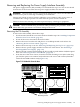
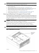
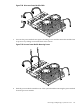

8. From the front of the server, locate the two hard drive backplane cables and disconnect
them.
Figure 7-22 PSI Module From the Front
chasnodvdasy
CPU Power Pod
Interface Cables
9. Remove the PSI assembly, along with the attaching cables, from the server chassis.
Installing the PSI Assembly
To install a PSI assembly, follow these steps:
CAUTION: Observe all ESD safety precautions while performing this procedure. Failure to
follow ESD safety precautions can result in damage to the server.
1. From the front of the chassis, position the power supply interface module against the recessed
ventilation panel.
2. Turn the server chassis around 180 degrees on the bench to enable access from the rear.
NOTE: It is assumed that you have removed the fan control board and CD/DVD optical
drive from the chassis.
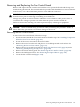
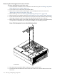
3. From the rear of the chassis, install the four PSI module mounting screws (Figure 7-21).
NOTE: You may need to slightly elevate the module off the floor of the chassis to align
the screws with their respective mounting holes, because the two power supply plug-in
connectors must float to enable proper engagement when a power supply module is inserted.
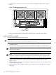
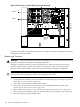
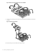
4. From the front of the chassis, connect the two hard drive backplane interface cables
(Figure 7-22).
5. Reinstall the fan control board including the CD/DVD optical drive. See “Installing the Fan
Control Board” (page 144).
6. Reinstall the two power supply modules. See “Installing a Hot-Swappable Power Supply”
(page 120).
142 Removing and Replacing Components