
HP Integrity cx2600 Operations and Maintenance Guide
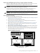
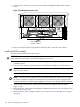
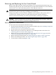
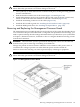
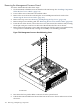
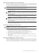
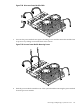
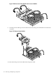

Figure 7-23 Fan Control Board
chasfnbrdxtnd
Fan
Control
Board
8. Remove the terminating connectors from the cables (Figure 7-24).
Figure 7-24 Fan Control Board Connectors
fncntbrd2
P4
P8
P3
P12
P2
P5
P1
P11
J1
J2
Fan
Control
Board
Mounting
Screw
9. Remove the single screw (M3 x .5 10mm long pan T10 crest cup stainless steel) located at
the top left corner of the fan control board, which secures the board to the standoffs on which
it is mounted.
10. Clear a pathway through the cables and slide the fan control board toward the front, until
its locking apertures clear the stand-off locks.
11. Remove the fan control board from the chassis.
12. Remove the fan control board from the chassis.
Installing the Fan Control Board
To install a fan control board, follow these steps:
144 Removing and Replacing Components