
HP Integrity cx2600 Operations and Maintenance Guide

Replacing the Management Processor Board Battery
A keep-alive battery is located on the under-side of the MP board, with a design lifetime of ten
years. This 3 volt CR2032 type battery can be accessed for replacement only when the MP board
is out of the system. To replace the battery, perform these steps:
CAUTION: Observe all ESD safety precautions while performing this procedure. Failure to
follow ESD safety precautions can result in damage to the server.
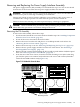
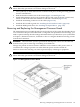
1. After removing the MP board from the server chassis, locate the battery on the underside
of the board assembly.
CAUTION: Do not overstress the battery retaining clip. This clip is easily broken. Lift the
battery just high enough to clear the battery holder. Failure to heed this warning can result
in damage to the clip.
2. Lift up on the battery retaining clip and push on the back of the battery with a flathead
screwdriver to remove it from its holder. Remove the battery.
WARNING! Lithium batteries can explode if mistreated. Do not recharge, disassemble, or
dispose of batteries in a fire. When discharged, do not throw batteries away, collect them
as small chemical waste. Failure to observe this warning can result in personal injury or
damage to equipment.
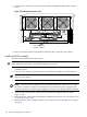
3. Lift up on the retaining clip and slide the replacement battery into its holder. Make sure the
positive side of the battery faces up.
Installing the Management Processor Board
CAUTION: Observe all ESD safety precautions while performing this procedure. Failure to
follow ESD safety precautions can result in damage to the server.
To install the MP board, follow these steps:
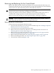
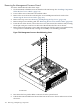
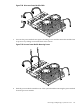
1. Position the MP board onto the three screws with the edge connectors aligned with the
corresponding cutouts on the rear section of the chassis (Figure 7-25).
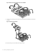
2. Fasten the two screws securing the DB-25 connector to the chassis rear panel.
3. Reconnect the low-profile ribbon connector to the system board.
4. Insert and tighten the two screws that secure the MP board to the three standoffs on the
system board.
5. Install the processor airflow guide. See “Installing the Processor Airflow Guide” (page 128).
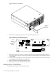
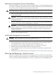
Removing and Replacing a System Processor
The server can include one or two processors. The processors are located on the system board
and are accessible after removing the top cover and airflow guides. Processor 0 (CPU 0) is located
closer to the chassis side panel and processor 1 (CPU 1) is located closer to the DIMM sockets.
Removing and Replacing a System Processor 147