
HP Integrity cx2600 Operations and Maintenance Guide
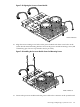
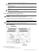


13. Locate the four front fan cables 1-4 near the system board, and remove the common harness
from the recession near the board’s edge. Pop the clips on the fan cable by pushing down
on the tab. By completely removing the cables, clips, and harness, this enables clearance for
removing the system board.
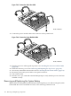
14. Remove the single noncaptive screw (M3 x 6mm long pan T-15/slot square cone stainless
steel) that secure the system board to chassis floor (Figure 7-46).
15. Slide the system board toward the front of the chassis to disengage the board locks.
16. Lift the board assembly from the chassis. Place it on an ESD-protected surface.
Installing the System Board
CAUTION: Observe all ESD safety precautions while installing the system board. Failure to
follow ESD safety precautions can result in damage to the server.
To install a system board, follow these steps:
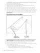
1. Position the replacement board assembly on its locating or locking posts (seven places) and
slide it toward the rear of the chassis. Use the four screws on the rear of the server to draw
the system board toward the EMI gasket until fully engaged.
2. When the system board assembly is fully engaged, replace and tighten the single screw
securing the board to the chassis (Figure 7-46).
3. Install the following connectors. (Use the connector hardware removed during board
removal.)
• SCSI LVD (left)
• Serial A console (right)
• Serial B (below Serial A console)
4. Return the fan cable 1-4, harness, and clips to their respective locations. Make sure the clips
snap into place. The harness fits between the system board and the vertical chassis surface.
5. Reconnect all connectors that were disconnected from the system board during board
removal.
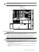
6. Replace the center support member that separates the PCI-X cage compartment from the
system board (Figure 7-47). Secure the center support in position with five screws. Re-dress
the cable harness that attaches to the support member.
7. Install the PCI-X card cage. See “Installing the PCI Card Cage Assembly” (page 133).
8. Install all airflow guides. See “Removing and Replacing Airflow Guides” (page 127).
9. Populate the newly installed system board with the following items, which are generally
the first removed from the board you are replacing:
• MP card. See “Removing and Replacing the Management Processor Board” (page 145).
• DIMM memory modules. See “Removing and Replacing System Memory DIMMs”
(page 128).
• CPU processors. See “Removing and Replacing a System Processor” (page 147).
10. Replace the server top cover. See “Removing and Replacing the Top Cover” (page 123).
11. Reconnect all external cables and power on the server.
12. Run the info cpu command at the EFI Shell prompt to verify that the processor works.
13. Review the system configuration in the EFI Shell and reconfigure settings as necessary.
Removing and Replacing the System Board 165