
HP Integrity cx2600 Operations and Maintenance Guide

NOTE: Remove the server top cover during this procedure, so you can observe the system
board LEDs and install assemblies. With the top cover removed, the system powers off after two
minutes of operation. After installing an assembly, apply power and immediately check for status
and symptoms. Use the MP to access error messages after the system has powered off.
To build up the system, follow these steps:
1. Disconnect power from the server power supply either at the cabinet or facility power
disconnect device.
WARNING! Ensure that the system is powered off and all power sources are disconnected
from the server prior to removing or installing server hardware.
Voltages are present at various locations within the server whenever a DC power source is
connected. This voltage is present even when the main power switch is turned off.
Failure to observe this warning can result in personal injury or damage to equipment.
2. If present, remove the following components from the system:
• Top cover
• The second power supply
• MP card
• CPU and power module (remove both CPUs if two are installed)
• All DIMMs
• All hard disks
• CD/DVD drive
NOTE: At a minimum hardware configuration, the system consists of the following:
• One power supply
• Power supply interface assembly
• System board
• Processor
• Memory
• Front panel status board
• HDD
• Disk drive backplane
• Fan control board
• Five fans
3. Connect power to the power supply; but do not power on the server at this time.
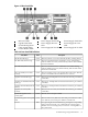
4. On the system board, ensure that the standby power (STBY) LED is lit and the BMC heartbeat
LED is flashing.
• If the STBY LED is not lit, replace the power supply, the power supply interface
assembly, or the system board.
• If the BMC heartbeat LED is not flashing, replace the system board.
5. To apply power, press the front panel Power button. Observe the power LED, the diagnostic
LEDs, and the system LED.
• If the fault LED on the power supply is lit, replace the power supply, the power supply
interface assembly, or the system board.
• If the front panel power LED is not lit, replace the power supply interface assembly,
the system board, or the front panel status board.
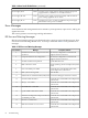
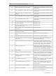
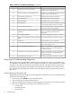
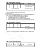
• To interpret the diagnostic and system LEDs, use Table 4-8.
Troubleshooting Using Offline Support Tools 69