
HP Integrity cx2600 Operations and Maintenance Guide
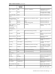
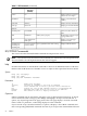
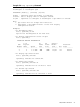
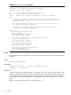

Table 4-10 Interpret Diagnostic and System LEDs (continued)
DescriptionSystem LEDDiag 4 LEDDiag 3 LEDDiag 2 LEDDiag 1 LED
The BMC is reporting a fatal error due
to missing DIMMs. Continue with the
build up procedure.
Flashing RedGreenOffOffRed
Replace the MP card or the system
board. For additional information, see
Table 4-3 (page 58) .
Any Other LED Status Display
12. Power off and disconnect power from the server. (If the system has shut itself down, only
disconnect power.) To power off the server and disconnect power at the cabinet or facility
power disconnect device, press the front panel Power button.
13. Install four DIMMs in the first quad.
14. To apply power, press the front panel Power button. Observe the power LED, the diagnostic
LEDs, and the system LED.
• If the fault LED on the power supply is lit, replace the faulty DIMMs or the system
board.
• If the front panel power LED is not lit, replace the faulty DIMMs or the system board.
• For additional information, see the SEL.
• To interpret the diagnostic and system LEDs, use Table 4-11.
Table 4-11 Interpret Diagnostic and System LEDs
DescriptionSystem LEDDiag 4 LEDDiag 3 LEDDiag 2 LEDDiag 1 LED
Boot in progress.Green or RedGreenGreenGreenGreen
When stable
For additional information, see
Table 4-3 (page 58).
Any Other LED Status Display
15. Power off and disconnect power from the server. (If the system has powered off, you only
need to disconnect power.) To power off the server, and disconnect power at the cabinet or
facility power disconnect device, press the front panel Power button.
16. Install one assembly or four DIMMs.
17. To apply power to the server, press the front panel Power button. Observe the power LED,
the diagnostic LEDs, and the system LED.
• If the fault LED on the power supply is lit, replace the newly installed assembly or the
system board.
• If the front panel power LED is not lit, replace the newly installed assembly or the
system board.
• For additional information, see the SEL.
• To interpret the diagnostic and system LEDs, see Table 4-3 (page 58).
18. To build up the server, repeat steps Step 15, Step 16, and Step 17 as required.
19. Install the top cover on the server chassis.
20. Restart the system.
Troubleshooting Using Offline Support Tools 71