
HP Integrity cx2600 Operations and Maintenance Guide


1 Controls, Ports, and Indicators
Introduction
This chapter describes the controls, ports, and indicators found on the front panel, rear panel,
and internal locations of the hp Integrity cx2600 Server.
Front Panel
The front panel of the hp Integrity cx2600 Server provides the controls and indicators commonly
used for operation.
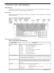
Figure 1-1 Front View of hp Integrity cx2600 Server
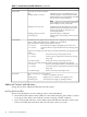
Switch/Button and LED Definitions
Table 1-1 Switch/Button and LED Definitions
DescriptionSwitch or Button
Sounds when an error has been detected during boot or operation.e-buzzer (behind front
grill)
One beep Processor absent or failing.
Two beeps Power supply malfunction.
Three beeps Memory malfunction.
Four beeps Management processor card malfunction.
Five beeps PCI I/O card malfunction.
Six beeps Critical system failure.
Seven beeps System board malfunction.
Remotely activate or deactivate the server locator LED through the LAN or locally by
pressing the Locator button on the front or rear panel. This device is used to help identify
or locate a particular server among many.
Locator LED and Button
These LEDs, together with the server LED, display system error and fault status. The
states of the LEDs can be decoded to identify an error or fault condition or the failing
Diagnostic LEDs (1 thru 4)
customer repair unit (CRU). (For more information on LEDs, see “Troubleshooting”
(page 53).)
Shows the activity status of the server LAN as follows:LAN LED
OFF System power is off.
Lit steady green LAN link established but LAN is inactive.
Flashing green LAN is active.
Introduction 9