
Installation Guide, Second Edition - HP Integrity cx2620
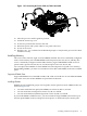
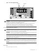
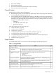

Figure 1-27 dc Power Supply Wire Connectors
Fault
DC Out DC In
Fault
DC Out DC In
rearview
dc Power
Supply Wire
dc Power
Supply Wire
dc Power
Supply Wire
dc Power
Supply Wire
2. Connect the dc power plugs into the outlet. The server goes into standby power mode as
soon as the power cable is connected to the power inlet.
NOTE: If the fans turn on, the system may be in full power-on mode. To exit full power-on
mode, press the Power button on the front grill until the power goes off and the fans stop
running.
3. Attach the M cable (25-pin) to the DB25 port on the server. The M cable has three connectors
labeled as follows:
• Console
• Remote
• UPS
4. Connect core I/O connections if needed.
5. Attach the connector labeled Console to the RS-232 female-to-female cable.
NOTE: The RS-232 cable is required. The cable is a direct-connect cable (pin 1-to-pin 1, pin
2-to-pin 2).
6. Connect the RS-232 cable to the emulation device.
Applying Standby Power to the Server
IMPORTANT: If the server has one bulk power supply (BPS), plug the power cable into the
receptacle labeled PWR 1.
To apply standby power to the server, follow these steps:
1. Locate the appropriate receptacle on the rear of the chassis. Plug the power cord into the
receptacle.
2. Observe the following LEDs at two different intervals to ensure the server is in the standby
power state.
Interval One After you plug the power cord into the server, the bulk power supplies
flash amber and an amber light is present on the hard disk drives.
Connecting Cables 47