
Installation Guide, Second Edition - HP Integrity cx2620

Interval Two Approximately 30 seconds later, the bulk power supplies flash green
and the amber light is still present on the hard disk drives. Standby
power is now on.
Core I/O Connections
The server has one core I/O card installed. Each core I/O card has an ilO MP. Each core I/O card
is oriented vertically and accessed from the back of the server. Use the core I/O board to perform
the following:
• Update firmware
• Access the console
• Use other features of the system
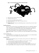
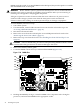
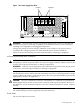
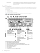
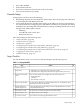
Figure 1-28 shows the locations of the cable connections on the server rear panel.
Figure 1-28 Connections, Port, Buttons, & LEDs
13
Keyboard USB
Port
7
RS-232 Serial Console
Port (console (iLO MP),
remote, UPS)
1
LVD/SE SCSI Port
2
iLO MP LAN (10/100
LAN) & LEDs
14
Mouse USB Port
8
USB Port
3
Gigabit Ethernet LAN
15
dc Power Supply
Wire
9
Serial Port A — This
port is disabled.
4
VGA Port
16
dc Power Supply
Wire
5
iLO MP Reset Button
10
Serial Port B — This port
is disabled.
6
Locator Button & LED
17
dc Power Supply
Wire
11
System Management
LAN (10/100/1000 LAN)
& LEDs
18
dc Power Supply
Wire
12
TOC Button
The following are the core I/O connections:
• One iLO MP LAN port (10/100 LAN)
• One system management LAN port (10/100/1000 LAN)
• One RS-232 local serial console port (console (iLO MP), remote, UPS)
• One USB keyboard connector
• One USB mouse connector
• Two USB ports
• VGA port (no access to iLO MP; EFI only)
48 Installing the System