
Installation Guide, Second Edition - HP Integrity cx2620

• Determine the physical access method to select and connect cables.
• Determine the iLO MP LAN configuration method and assign an IP address if necessary.
Determining the Physical iLO MP Access Method
Before you can access the iLO MP, you must first determine the correct physical connection
method. The iLO MP has a separate LAN port from the system LAN port. It requires a separate
LAN drop, IP address, and networking information from that of the port used by the operating
system.
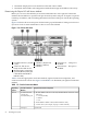
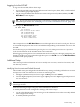
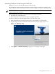
Figure 1-30 shows the server rear ports. See the HP Integrity and HP 9000 iLO Management Processor
Operations Guide for more information on how to access the iLO MP.
Figure 1-30 Server Rear Ports
7
Serial Port A — This port is
disabled.
4
USB Port. (Keyboard)
1
iLO MP LAN Port. (10/100
LAN)
5
USB Port. (Mouse)
2 8
VGA Port. EFI Access
Only. No iLO MP Access.
Serial Port B — This port is
disabled.
6
USB Port
3
RS-232 Serial Console Port
(Console/Remote/UPS). (M
Cable & RS-232 DB-9F to
DB-9F Cable)
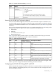
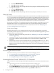
Table 1-5 lists the appropriate connection method, required connection components, and
connectors to the host console. Use Figure 1-30 andTable 1-5 to determine your physical connection
method.
Table 1-5 Console Connection Matrix
Required Connection ComponentsConsole Connection
Method
Operating
System
1. M-cable: DB25 connector on one end, and three DB-9F connectors on the
other end:
• Console (ilO MP)
• Remote
• UPS
2. RS-232 DB-9F to DB-9F cable (modem eliminator cable)
3. Console device (for example, a laptop or ASCII terminal)
Local RS-232 serial
console port
remote/modem port
HP-UX
10/100 LANLAN port
52 Installing the System