
Site Preparation Guide, Second Edition - HP Integrity cx2620 Server

IMPORTANT: Regardless of the grounding connection method used, the raised floor should be
grounded as an absolute safety minimum.
HP recommends the following approaches to create an effective and safe 2-foot by 2-foot signal
reference grid::
Good Use the raised floor structure as a ground grid. In this case, the floor must be designed
as a ground grid with bolted down stringers and corrosion-resistant plating (to provide
low resistance and attachment points for connection to service entrance ground and
HP computer equipment). The use of conductive floor tiles with this style of grid
further enhances ground performance. The structure needs to be mechanically bonded
to a known good ground point.
Better Add a grounded #6 AWG (16mm) minimum copper wire grid mechanically clamped
to floor pedestals and properly bonded to the building or site ground.
Best Add a grounding grid to the subfloor. Build the grounding grid with copper strips
mounted to the subfloor. Use strips that are 0.032 inches (0.08 cm) thick and a minimum
of 3.0 inches (8.0 cm) wide.
Connect each pedestal to four strips using 1/4-inch (6.0-mm) bolts tightened to the
manufacturer’s torque recommendation.
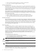
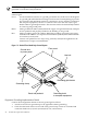
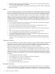
Figure 2-1 Raised Floor Metal Strip Ground System
Ground wire
to power panel
Floor panel
Hex bolt
Grounding clamp
Band and pedestal
Grounding braid
to computer equipment
Grounding grid eleme
n
Equipment Grounding Implementation Details
Connect all HP equipment cabinets to the site ground grid as follows:
1. Attach one end of each ground strap to the applicable cabinet ground lug.
2. Check that the braid contact on each end of the ground strap consists of a terminal and
connection hardware (a 1/4-inch (6.0-mm) bolt, nuts, and washers).
28 General Site Preparation Guidelines