
User Service Guide, Third Edition - HP Integrity cx2620 Server
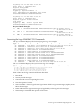


Installing the Latest Version of the Firmware on the Server
To install the latest version of the firmware on the server, follow these steps:
1. Initiate a server console session.
2. Insert the CD with the copy of the latest version of the firmware.
3. Using the EFI Boot Manager menu, boot to the drive that contains the CD with the updated
firmware.
4. Follow the instructions to update the firmware.
Server Interface (System Console)
All system console connections (VGA, USB, local RS-232 and iLO MP LAN) are made through
the I/O port connector on the front of the server, through the local I/O cable.
HP-UX uses the RS-232 serial text connection to a dumb terminal, or to terminal emulator software
running on a PC, to control server operations locally. All other connections are unsupported.
HP-UX alternatively uses the iLO MP’s 10/100 BT LAN connection over a private network, to
control one or more server operations -- locally through Telnet or Secure Shell (SSH), or remotely
over a public network through a web GUI.
Troubleshooting Tips
RS-232 connection: If a dumb terminal/PC running terminal emulation software is attached to
the iLO MP “local” port and does not respond to a Ctrl+B key sequence (and the terminal is
running 9600 baud, 8 data bits, is ONLINE, etc.), it is possible that the iLO MP is not operational
or functional.
Telco Alarm
The server uses telco alarm monitoring to help monitor equipment and identify the cause of
physical system problems. Alarm processing is managed through the Baseboard Management
Controller (BMC). This option is available at an additional cost.
The fan controller provides an interface to a set of three telco alarm signals. Each alarm signal
has three pins (normally open, normally closed, and common) that are connected through a cable
to a connector on the back bulkhead of the server. The BMC sets off any combination of these
three alarm signals as it deems necessary through the use of 12C commands.
NOTE: Although HP provides telco alarm functionality, you design the alarm signal output
according to your environment and specifications. For information on how to program the telco
alarm, see the telco alarm documentation.
Alarm Levels
There are three levels of telco alarms and many sources of alarm condition.
Critical Alarm Attached to the System State LED; triggers when LED is flashing red at
2 Hz.
Major Alarm Attached to the System State LED; triggers when LED is flashing yellow
at 1Hz.
148 Troubleshooting