
User Service Guide, Third Edition - HP Integrity cx2620 Server


Power Alarm The BMC controls this alarm based on the state of system power.
CAUTION: Failure to recognize an alarm condition can result in loss of data or damage to
equipment.
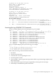
Limitations
Telco alarm performance limitation includes:
• You can not clear the red system state LED until you reboot the server.
• You cannot turn off the telco alarm until you reboot the server.
• You can clear the yellow system state LED when the SEL is read, even though the warning
condition still exists.
NOTE: The power alarm only mirrors the state of system (main) power. For example, BMC
sets the power alarm when system power is off, and clears it when system power is on. Specific
operations, such as manually turning the power alarm off when system power is off, depend on
the design and automation of the external alarm management device.
• Powering off the system does not affect the system state LED.
• Turning off the main power causes the power LED to flash (as long as DC power remains
connected to the server).
• Disconnecting all power cables from the chassis causes all the LEDs to go dark.
• The server does not provide any audio capabilities.
• You cannot turn on or off the generated alarm signals from the server.
• You must mechanize and design the external alarm signal manager provided.
Relay Interface
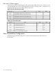
Table 5-17 lists three dry contact relays, all located on the fan control board. They are identified
on the board as K1, K2, or K3 and assigned the following alarm and signal names. The dry contact
relays communicate information to the telco alarm monitor, so that any problems that occur on
a system are indicated by the LEDs on the alarm panel.
Table 5-17 Relay Numbering
SignalAlarmRelay
(Alarm 0)CriticalRelay K1
(Alarm 1)MajorRelay K2
(Alarm 2)PowerRelay K3
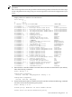
Signals Provided from Each Relay
Table 5-18 lists three signals provided from each relay through the DB-9F connector.
Telco Alarm 149