
User Service Guide, Third Edition - HP Integrity cx2620 Server
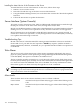


Table 5-18 Relay Signals
DescriptionAbbreviationSignal
This signal must be pulled up to no more than 24V above Return external
to the system.
• When the alarm is not activated, this signal is open (electrically high since
pulled up externally).
• When the alarm is activated, this signal is connected by a dry contact
relay to the Return pin.
The external pull-up resistor must limit the current to no more than 1 Amp.
(NO)Normally Open
This signal must be pulled up to no more than 24V above Return external
to the system. When the alarm is not activated, this signal is connected by
a dry contact relay in the system to the Return pin. When the alarm is
activated, this signal opens (electrically high since pulled up externally).
The external pull-up resistor must limit the current to no more than 1 Amp.
(NC)Normally Closed
This is the return path for both the Normally Open and Normally Closed
signals.
(COM)Return
DB9 Pin-Out
Table 5-19 lists the assigned relay, pin number, alarm, and signal name for each pin of the DB9
connector.
Table 5-19 Relay Numbering
SignalAlarmPin #Relay
ALARM0_NOCritical Normally_Open1K1
ALARM0_NCCritical Normally_Closed2
ALARM0_COMCritical Return6
ALARM1_NOMajor Normally_Open7K2
ALARM1_NCMajor Normally_Closed8
ALARM1_COMMajor Return3
ALARM2_NOPower Normally_On4K3
ALARM2_NCPower Normally_Off5
ALARM2_COMPower Return9
Figure 5-3 shows the DB9 pins.
150 Troubleshooting