
User Service Guide, Third Edition - HP Integrity cx2620 Server
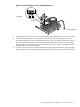
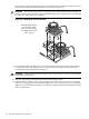
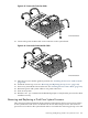
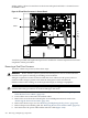
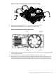

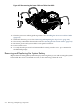

Figure 6-43 Aligning the Processor Power Module
Front of Chassis
16. Align the two mounting screw holes on the power module with their screw holes on the
system board’s metal mounting bracket. Screw in the power module mounting screws (M3
x 23mm long pan T15 crest cup stainless steel, 2 per CPU).
Figure 6-44 Installing the Processor Module Power Pod Mounting Screws
Front of Chassis
17. Connect the processor module turbo fan power cable to the connector on the system board.
204 Removing and Replacing Components