
User Service Guide, Third Edition - HP Integrity cx2620 Server
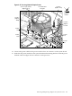
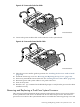

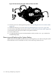

airflow guides. CPU 0 is located closer to the chassis side panel and CPU 1 is located closer to
the DIMM sockets.
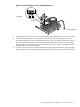
Figure 6-47 Dual-Core Processors in Server Chassis
CPU 0
CPU 1
F
R
O
N
T
A tool kit is provided with replacement processors. An IPF-CPU tool kit is required for successful
completion of these procedures.
Removing a Dual-Core Processor
To remove a dual-core processor, follow these steps:
WARNING! Ensure that the system is powered off and all power sources are disconnected
from the server prior to removing or installing server hardware.
Voltages are present at various locations within the server whenever a DC power source is
connected. This voltage is present even when the main power switch is turned off.
Failure to observe this warning can result in personal injury or damage to equipment.
CAUTION: Observe all ESD safety precautions while performing processor removal. Failure
to follow ESD safety precautions can result in damage to the server.
1. If rack-mounted, extend the server out from the rack until it stops. See “Installing Components
When the Server Is in a Rack” (page 154).
2. Power off the server. Disconnect all external cables.
3. Remove the server from the rack and place it on an ESD-protected work surface. See
“Removing the Server From a Rack” (page 155).
4. Remove the chassis top cover. See “Removing and Replacing the Top Cover” (page 158).
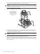
5. Remove the processor airflow guide. See “Removing the Processor Airflow Guide” (page 176).
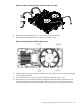
6. Disconnect the CPU power cable and the turbo fan cable (Figure 6-48).
206 Removing and Replacing Components