
User Service Guide, Third Edition - HP Integrity cx2620 Server
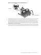
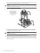
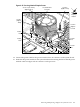
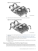
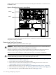
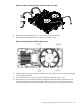

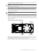
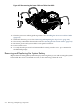

Figure 6-48 Disconnecting the Power Cable and Turbo Fan Cable
7. Release the two mounting captive screws on the processor module.
8. Release the heatsink captive screws as shown in (Figure 6-49).
Figure 6-49 Releasing the Heatsink Captive Screws
9. Slide the sequencing retainer plate toward the rear of the chassis to open the hole in the edge
of the turbo fan heatsink.
10. Insert the IPF-CPU tool into the processor locking mechanism (Figure 6-40).
11. Unlock the processor-locking mechanism using the Allen (hex) side of the IPF-CPU tool.
Insert the Allen (hex) side of the IPF-CPU tool into the lock access hole that runs down
through the edge of the turbo fan heatsink. Unlock the processor locking mechanism by
Removing and Replacing a Dual-Core System Processor 207