
User Service Guide, Third Edition - HP Integrity cx2620 Server

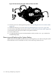

rotating the IPF-CPU tool counterclockwise 180 degrees. Verify that the processor-locking
mechanism is rotated into the unlocked position.
CAUTION: The zero insertion force (ZIF) socket for the processor is locked and unlocked
by half a full turn of the IPF-CPU tool. The counterclockwise 180 degree rotation (half-turn)
unlocks the socket. A clockwise 180 degree rotation locks the socket. Attempting to turn the
locking mechanism more than 180 degrees can severely damage the socket.
12. Lift the processor straight up and out of the chassis. Place the processor into an antistatic
container upside-down to ensure the pins do not get bent.
Replacing a Dual-Core Processor
The system board can support either one or two dual-core processors. The following procedure
is applicable to installation of CPU 0 or CPU 1. CPU 0 is located closer to the chassis side panel
and CPU 1 is located closer to the DIMM sockets. You must install CPU 0 before installing CPU
1.
WARNING! Ensure that the system is powered off and all power sources are disconnected
from the server prior to removing or installing server hardware.
Voltages are present at various locations within the server whenever a DC power source is
connected. This voltage is present even when the main power switch is turned off.
Failure to observe this warning can result in personal injury or damage to equipment.
CAUTION: Observe all ESD safety precautions while performing processor removal. Failure
to follow ESD safety precautions can result in damage to the server.
NOTE: Installation instructions are provided with replacement processors. Read those
instructions carefully. Changes in processor design and installation may have occurred since
this procedure was written. Always follow the instructions provided with a replacement processor.
To replace a dual-core processor, follow these steps:
1. If rack-mounted, extend the server out from the rack until it stops. See “Installing Components
When the Server Is in a Rack” (page 154).
2. Power off the server. Disconnect all external cables.
3. Remove the server from the rack and place it on an ESD-protected work surface. See
“Removing the Server From a Rack” (page 155).
4. Remove the chassis top cover. See “Removing and Replacing the Top Cover” (page 158).
5. Remove the processor airflow guide. See “Removing the Processor Airflow Guide” (page 176).
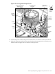
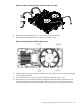
6. Ensure that the processor locking mechanism is rotated to the unlocked position (Figure 6-40).
7. Inspect the pins of the processor you are installing. Verify that processor pins are not bent.
8. Insert the Allen (hex) side of the IPF-CPU tool into the lock access hole that runs down
through the edge of the turbo fan heatsink before you place the heatsink on the system
board. As you place the turbo fan heatsink onto the system board, guide the tool until it
connects.
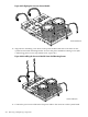
9. Use the four locator posts on the heatsink and the turbo fan power cable to properly align
the processor on the system board. The four locator posts fit into locator holes on the system
208 Removing and Replacing Components