
User Service Guide, Third Edition - HP Integrity cx2620 Server
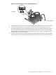
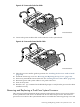


board processor mount. Position the turbo fan power cable so that it is located on the side
of the heatsink that faces the front of the chassis.
CAUTION: Do not press the processor module into the socket. When properly aligned, the
processor pins seat into the socket. No additional pressure is required. You can damage the
pins if you apply too much pressure.
10. Properly align the processor so the processor and heatsink face the rear of the chassis.
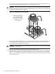
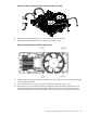
11. Use the Allen (hex) side of the IPF-CPU tool to lock the processor in place on the system
board. To do this, insert the tool into the hole that runs down the side of the heatsink and
rotate it clockwise 180 degrees.
CAUTION: Do not rotate the cam on the processor socket too far. You can damage the
locking mechanism.
12. Slide the sequencing retainer plate toward the front of the chassis.
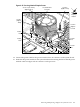
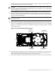
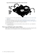
13. Tighten the four captive screws of the heatsink in the order shown in Figure 6-50. Using a
criss-cross torquing pattern, alternatively tighten each screw 1/2 turn so as not to completely
tighten one screw in before the others. Continue this sequence until the heatsink is secured
to the system board.
Figure 6-50 Securing the Heatsink Captive Screws
Screw 4
Tighten Last
Screw 3
(Tighten Third)
Screw 1
Tighten First
Screw 2
Tighten Second
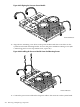
14. Align the two mounting screw holes on the processor module with the screw holes on the
system board metal mounting bracket. Screw in the processor module mounting screws
(M3 x 23mm long pan T15 crest cup stainless steel, two per CPU).
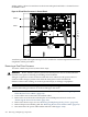
15. Connect the CPU power cable and the turbo fan cable to the connectors on the system board.
Removing and Replacing a Dual-Core System Processor 209