
User Service Guide, Third Edition - HP Integrity cx2620 Server


1. If rack-mounted, extend the server out from the rack until it stops. See “Installing Components
When the Server Is in a Rack” (page 154).
2. Power off the server. Disconnect all external cables.
3. Remove the server from the rack and place it on an ESD-protected work surface. See
“Removing the Server From a Rack” (page 155).
4. Remove the chassis top cover. See “Removing and Replacing the Top Cover” (page 158).
5. Remove all airflow guides. See “Removing and Replacing Airflow Guides” (page 175).
6. Remove the PCI-X card cage. See “Removing and Replacing the PCI-X Card Cage ” (page 167).
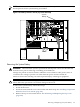
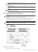
7. Loosen the five captive screws (T-15) that secure the center support member separating the
PCI-X cage compartment from the system board area to the chassis (Figure 6-54). Remove
the cable harness attached to the support member and remove the support member from
the server chassis.
Figure 6-54 Removing the Center Support Member
8. Remove the CPU processors. See “Removing and Replacing a Single-Core System Processor”
(page 192)
or “Removing and Replacing a Dual-Core System Processor” (page 205).
9. Remove the DIMM memory modules. See “Removing and Replacing System Memory
DIMMs” (page 177).
10. Remove the iLO MP card. See “Removing the iLO MP Card” (page 191).
11. Label and disconnect all cables connected to the system board.
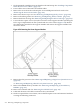
12. On the rear panel of the server chassis, remove the noncaptive screws and connector hardware
securing the following connectors:
214 Removing and Replacing Components