
User Service Guide, Third Edition - HP Integrity cx2620 Server

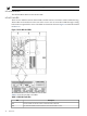
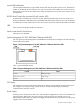
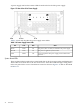
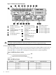
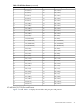
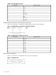

Figure 1-7 HP Integrity cx2620 Server Rear Panel
13
Keyboard USB Port
7
RS-232 Serial Console
Port (console (iLO MP),
remote, UPS)
1
LVD/SE SCSI Port
2 14
iLO MP LAN (10/100
LAN) Port and LEDs
Mouse USB Port
15
DC Power Supply Wire
8
USB Port
3
Gigabit Ethernet LAN A
(10/100/1000 LAN) Port
and LEDs
16
DC Power Supply Wire
9
Serial Port A: This port is
disabled.
17
DC Power Supply Wire
18
DC Power Supply Wire
104
Serial Port B: This port is
disabled.
VGA Port
5
iLO MP Reset Button
11
System Management
LAN B (10/100/1000
LAN) Port and LEDs
6
Locator Button and LED
12
TOC Button
LVD/SE SCSI
Two Ultra 3, 68-pin SCSI connectors are located on the host bus adapter (HBA) located in PCI-X
slot 1. The upper connector supports SCSI channel A and the lower connector supports SCSI
channel B.
iLO MP LAN LEDs
The four iLO MP LAN LEDs display the status of the iLO MP LAN.
Table 1-5 iLO MP LAN LEDs
StatusStateColorLocationLED
Self test is active. iLO MP is running self test.Off/OnYellowTopSelf Test
No Link detected or 100BT is active. Indicates
10BT LAN activity. 10BT link established.
Off/Flashing/Lit
Steady
Green2nd from top10BT
No Link detected or 10BT is active. Indicates
100BT LAN activity. 100BT link established.
Off/Flashing/Lit
Steady
Green2nd from
bottom
100BT
Standby power is not applied to iLO MP LAN
circuits. Power is connected to the server but
the server is not on.
Off/OnGreenBottomStandby Power
32 Overview