
User Service Guide, Third Edition - HP Integrity cx2620 Server

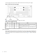

Locator LEDs and Button
Locator LEDs and buttons are provided on the front and rear panels of the server. The buttons
enable or disable the locator function. You can activate the locator LED from a remote location
through the LAN. The locator LED is lit to help call attention to locate the server when it is one
among many.
RS-232 Serial Console Port (console (iLO MP), remote, UPS)
25-pin female serial data bus connector for the optional iLO MP. This connector connects to a
three-port breakout cable (HP P/N A6144-63001) with individual connectors for Console, Remote
and UPS. The Console connector becomes the console connection when the iLO MP is installed.
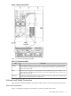
USB
Four universal serial bus (USB 2.0) connectors.
Serial A and Serial B Console Ports
These ports are disabled.
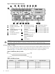
System Management 10/100/1000 Base-T Ethernet LAN B LEDs
The rear panel system management 10/100/1000 base-T Ethernet LAN B port has the following
status and activity LEDs.
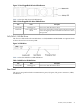
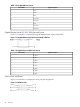
Figure 1-10 System Management 10/100/1000 Base-T Ethernet LAN B Port LEDs
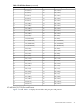
Table 1-9 lists link LED output.
Table 1-9 System Management 10/100/1000 base-T Ethernet LAN B Port LEDs
OutputLink LED
Blinking OrangeActivity
Solid OrangeLink with no activity
OffNo link
TOC Button
The Transfer of Control (TOC) button halts all system processing and I/O activity and restarts
the computer system preserving system memory contents and leaving the iLO MP in
communication with the console.
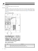
Power Supply
Primary power connection for the server. The standard configuration of the server includes two
power supplies. While only one power supply can be used to power the HP server, N+1
redundancy requires that a second power supply be installed. In normal operations, both power
supplies are in use at all times.
Controls, Ports, and LEDs 35