
User Service Guide, Third Edition - HP Integrity cx2620 Server

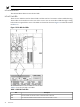
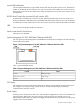
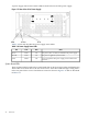
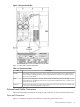
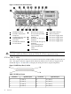
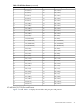
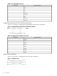

Figure 1-13 Server Ports and Connectors
13
Keyboard USB Port
7
RS-232 Serial Console
Port (console (iLO MP),
remote, UPS)
1
LVD/SE SCSI Port
2 14
iLO MP LAN (10/100
LAN) Port
Mouse USB Port
15
DC Power Supply Wire
8
USB Port
3
Gigabit Ethernet LAN A
(10/100/1000) Port
16
DC Power Supply Wire
9
Serial Port A: This port is
disabled.
17
DC Power Supply Wire
4
VGA Port
18
DC Power Supply Wire
10
Serial Port B: This port is
disabled.
5
iLO MP Reset Button
6
Locator Button
11
System Management
LAN B (10/100/1000
LAN)
12
TOC Button
CAUTION: To protect against intra-building lighting surges, use shielded cables that are
grounded at both ends. Failure to heed this caution can result in equipment damage.
SCSI Port, Ultra 3, 68-Pin
Two Ultra 3, 68-pin SCSI connectors are located on the host bus adapter (HBA) located in PCI-X
slot 1. The upper connector supports SCSI channel A and the lower connector supports SCSI
channel B. Figure 1-14 and Table 1-12 display the SCSI port Ultra 3, 68-pin and pinouts.
Figure 1-14 SCSI Port, Ultra 3, 68-Pin
Table 1-12 SCSI Port Pinouts
Signal DescriptionPin NumberSignal DescriptionPin Number
S35 (–DB 12)35S1 (+DB 12)1
S36 (–DB 13)36S2 (+DB 13)2
S37 (–DB 14)37S3 (+DB 14)3
S38 (–DB 15)38S4 (+DB 15)4
38 Overview