
User Service Guide, Third Edition - HP Integrity cx2620 Server
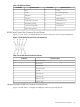
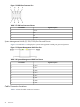
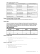

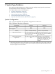
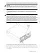
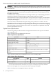
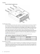

Figure 1-18 USB Port Connector Pins
Table 1-17 USB Port Connector Pinouts
Signal DescriptionPin Number
+5VDC1
MR2
PR3
Ground4
System Management LAN B (10/100/1000) Port Pins and Pinouts
Figure 1-19 and Table 1-18 display the system management LAN B port pins and pinouts.
Figure 1-19 System Management LAN B Port Pins
Table 1-18 System Management LAN B Port Pinouts
Signal DescriptionPin Number
BI_DA+1
BI_DA-2
BI_DB+3
BI_DC+4
BI_DC-5
BI_DB-6
BI_DD+7
BI_DD-8
Cable Connector Locations
Table 1-19 lists the cable connector locations.
42 Overview