
User Service Guide, Third Edition - HP Integrity cx2620 Server


Cooling
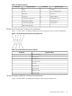
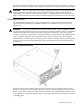
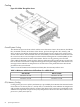
Figure 2-3 Airflow Through the Server
Overall System Cooling
The cabinet incorporates front to back airflow across the entire chassis. Four 80 mm, dual blade
fans, mounted vertically in the front of the chassis, push air through the CPU, memory, and
PCI-X sections. One 80 mm, dual blade fan and the internal power supply fans cool the lower
section of the chassis. The five 80 mm fans are controlled by circuits of the fan control board. The
fan control circuits receive fan input from the baseboard management controller (BMC) on the
system board, and return fan status information. The fan circuit generate power and the
pulse-width-modulated control signals to the fans and monitor the speed indicator signals from
each of the fans. Fan failures are reported through the front panel diagnostic LEDs and in error
messages. Room ambient air temperature is sensed on the front panel LED status board and
provided to the system board.
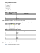
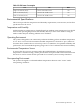
Table 2-6 lists the minimum and maximum CFM (cubic feet minute) airflow rates.
Table 2-6 Minimum and Maximum Airflow Rates for cx2620 Chassis
Without Air BaffleWith Air Baffle
Minimum: 166 CFMMinimum: 146 CFM
Maximum: 216 CFMMaximum: 185 CFM
CPU/Memory Cooling
Cooling for the processors (CPUs) and memory is provided by three 80 mm fans mounted in the
front of the server chassis (fans 2, 3, and 4). Fan 2 is controlled by room ambient air temperature
and provides air through the memory section of the chassis. Fans 3 and 4 are controlled by room
ambient air temperature and processor (CPU) temperature. These two fans direct airflow across
processor 1 (fan 4) and 2 (fan 3).
50 System Specifications