
User Service Guide, Third Edition - HP Integrity cx2620 Server


NOTE: The RS-232 cable is not supplied by HP.
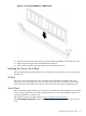
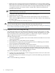
1. Connect the DC power supply wires to the DC terminal block at the rear of the DC power
supply (Figure 3-27).
Connect both of the plus (+) terminals to return.
Connect both of the minus (-) terminals to -48V.
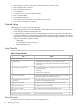
Figure 3-27 DC Power Supply Wire Connectors
2. Connect the DC power plugs into the outlet. The server goes into standby power mode as
soon as the power cable is connected to the power inlet.
NOTE: If the fans turn on, the system may be in full power-on mode. To exit full power-on
mode, press the Power button on the front grill until the power goes off and the fans stop
running.
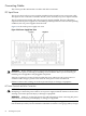
3. Attach the M cable (25-pin) to the DB25 port on the server. The M cable has three connectors
labeled as follows:
• Console
• Remote
• UPS
4. Connect core I/O connections if needed.
5. Attach the connector labeled Console to the RS-232 female-to-female cable.
NOTE: The RS-232 cable is required. The cable is a direct-connect cable (pin 1-to-pin 1, pin
2-to-pin 2).
6. Connect the RS-232 cable to the emulation device.
Applying Standby Power to the Server
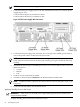
IMPORTANT: If the server has one bulk power supply (BPS), plug the power cable into the
receptacle labeled PWR 1.
To apply standby power to the server, follow these steps:
84 Installing the System