
User Service Guide, Third Edition - HP Integrity cx2620 Server
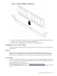


1. Locate the appropriate receptacle on the rear of the chassis. Plug the power cord into the
receptacle.
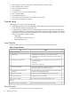
2. Observe the following LEDs at two different intervals to ensure the server is in the standby
power state.
Interval One After you plug the power cord into the server, the bulk power supplies
flash amber and an amber light is present on the hard disk drives.
Interval Two Approximately 30 seconds later, the bulk power supplies flash green
and the amber light is still present on the hard disk drives. Standby
power is now on.
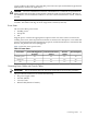
Core I/O Connections
The server has one core I/O card installed. Each core I/O card has an ilO MP. Each core I/O card
is oriented vertically and accessed from the back of the server. Use the core I/O board to perform
the following:
• Update firmware
• Access the console
• Use other features of the system
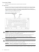
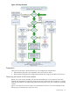
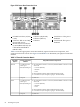
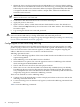
Figure 3-28 shows the locations of the cable connections on the server rear panel.
Figure 3-28 Connections, Port, Buttons, & LEDs
13
Keyboard USB Port
7
RS-232 Serial Console
Port (console (iLO MP),
remote, UPS)
1
LVD/SE SCSI Port
2 14
iLO MP LAN (10/100
LAN) Port and LEDs
Mouse USB Port
15
DC Power Supply Wire
8
USB Port
3
Gigabit Ethernet LAN A
Port and LEDs
16
DC Power Supply Wire
9
Serial Port A: This port is
disabled.
17
DC Power Supply Wire
4
VGA Port
18
DC Power Supply Wire
10
Serial Port B: This port is
disabled.
5
iLO MP Reset Button
6
Locator Button and LED
11
System Management
LAN B (10/100/1000
LAN) Port and LEDs
12
TOC Button
The following are the core I/O connections:
• One iLO MP LAN port (10/100 LAN)
• One system management LAN port (10/100/1000 LAN)
Connecting Cables 85