
BladeCluster Solution Manual


NOTE: You cannot use ports 11 and 12 at the same time.
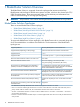
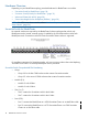
• BladeCluster Ports (13-18)
◦ Each BladeCluster port supports four transmit/receive fiber pairs. However, one
transmit/receive fiber pair in each of ports 16 and 18 is not used.
• Fiber (1-4)
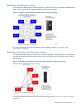
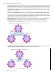
Processor Switch (P-Switch) for BladeCluster
No external switches are required by the BladeCluster topologies that include NonStop NS16000
series systems. Instead, external routing is handled by the processor switches within each NonStop
NS16000 series node. Coexistence with 6700 series ServerNet Cluster switches is supported:
For installation instructions for the processor switch PICs, ask your service provider to refer to the
Replacing a Processor Switch online help.
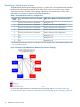
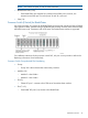
Processor Switch Group-Module-Slot Numbering
• Group:
◦ Group 100 is the enclosure that contains the p-switches.
• Module (2-3):
Module 2 is the X fabric.◦
◦ Module 3 is the Y fabric.
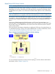
• Slot (2):
◦ Cluster PIC port 1 connects to the 6700 series ServerNet cluster switches.
• Slot (7 or 9):
◦ Quad MMF PIC ports (1-4) connect to the BladeCluster.
Hardware Overview 19