
BladeCluster Solution Manual

Cable Management Procedure for the ACH
The cable management system for the ACH consists of a cable management tray attached to the
rear side of the ACH. The tray has 10 cable management cartridges used to secure the MTP fiber
cables. At each side of the tray, a vertical radius guide (VRG) routes the cables up or down the
rack while maintaining a minimum bend radius. Perform this procedure for each ACH in the
BladeCluster zone.
On the back of each ACH:
NOTE: Keep dust covers in place on fiber cable ends until you are ready to connect them.
1. Connect the MTP-4LC or MTP-MTP fiber cables to the ACH connectors, as indicated by the
cable labels.
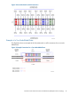
2. Each cable management cartridge has four slots numbered 1 to 4. Guide four cables at a
time to the slots in the cartridge that most closely align with the connectors on the ACH.
3. Open the cartridge’s blue latch and place the four cables into the four slots. The section of
cable between the connector and the cable management cartridge should be slightly loose,
not tight.
4. After all the cables are in the cartridge, close the blue latch. The cable management cartridge
acts as a strain relief for the fiber cables when the latch is closed.
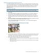
Figure 9 shows two fiber cables routed through slots 1 and 2 of the cable management
cartridge with the latch closed.
Figure 9 Cables Routed Through Cable Management Cartridge
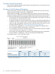
5. Determine which side of the rack to route the cables to. HP recommends that cables to the left
of cartridge 5, and including cartridge 5, be routed to the left side of the rack and that the
cables to the right of cartridge 5 be routed to the right side of the rack.
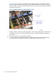
6. Route cables around the center radius control of each cartridge:
• Cables going to the left side of the rack are routed around the right side of the cartridge’s
center radius control.
• Cables going to the right side of the rack are routed around the left side of the cartridge’s
center radius control.
Advanced Cluster Hub (ACH) Description 41