
BladeCluster Solution Manual
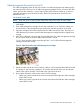
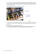
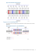
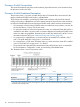

Figure 10 (page 42) shows two cables routed in opposite directions. One cable is routed
around the right side of the center radius control and then directed to the left side of the rack.
The other cable is routed around the left side of the center radius control and then directed to
the right side of the rack.
Figure 10 Cables Routed Around Center Radius Control
7. Route the cables out of the assembly through the vertical radius guide (VRG). The VRGs direct
the cables up or down in the rack while maintaining a 25-mm bend radius and supplying
strain relief.
8. Use Velcro straps to secure the cable to the VRG.
9. Connect the other end of the fiber cables to the appropriate ports on the ServerNet switch,
as indicated by the cable label. Wind excess cable around containment spools.
42 Advanced Cluster Hubs (ACHs)