
BladeCluster Solution Manual

Processor Switch Connections
This section describes the processor switch hardware, physical dimensions, and connections from
the processor switch to the ACH.
Processor Switch Hardware Description
The processor switch, or p-switch, provides the first level of ServerNet fabric interconnect for the
Integrity NonStop NS16000 series nodes in a BladeCluster.
The p-switches are installed in a NonStop NS16000 series enclosure and provide the external
routing in the nodes in a BladeCluster (as well as internal routing for the processors in that enclosure).
P-switches for BladeClusters that use NonStop NS16000 series nodes have these characteristics:
• All connections to the NonStop NS16000 nodes are made from two p-switches, one each for
the X and Y fabrics, in Group 100 of each node.
• To reduce the number of connections between the nodes, an Advanced Cluster Hub (ACH) is
installed for each fabric. Processor switch connections between the NonStop NS16000 series
nodes are made using Multifiber Termination Push-on MTP-4LC cables via the ACH. For more
information about the ACH, see “Advanced Cluster Hubs (ACHs)” (page 38).
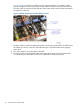
• For connectivity to a BladeCluster, a p-switch must have quad MMF PICs installed in slots 7
and 9. The quad MMF PICs occupy ports 1–4 in the slots.
• For connectivity to a 6700 series ServerNet cluster, a p-switch must have cluster PICs installed
in slot 2. The cluster PICs occupy ports 1–2 in the slot.
• The p-switches are supported by the Maintenance Entity (ME) firmware which is responsible
for the initialization, configuration, control, and monitoring of the BladeCluster.
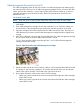
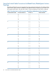
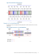
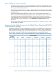
This illustration shows a view of a processor switch.
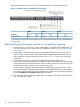
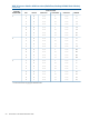
HeightDepthWidth
cmincmincminDimensions
13.35.362.224.548.319.0Processor switch (p-switch)
1
1
A processor switch weighs 70 pounds (32.8 kilograms). For power and environmental specifications, see the NonStop
NS16000 Series Planning Guide.
48 Connections to the Advanced Cluster Hubs