
BladeCluster Solution Manual

Before Cabling the Processor Switches
• Verify that a pair of ACHs (one for each external fabric) is installed for the BladeCluster. One
pair of ACHs supports up to five NonStop NS16000 series nodes. For installation instructions,
see “Advanced Cluster Hubs (ACHs)”.
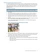
• Verify that the processor switches in group.module locations 100.2 and 100.3 of the NonStop
NS16000 series node that is being added to the BladeCluster have quad MMF PICs installed
in slots 7 and 9.
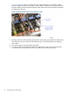
• If necessary, install the quad MMF PICs in slots 7 and 9. This procedure can be done one
fabric at a time without requiring either a system load or a system power cycle. For instructions
for installing ServerNet switches for BladeCluster, ask your service provider to refer to the
OSM Replacing P-switch online help. Your service provider should not connect any fiber-optic
cables to the ACH until prompted by the OSM Add Node To ServerNet Cluster guided
procedure.
• Check that the cables are labeled at both ends, indicating the node, fabric, processor switch
slot, and ACH port number.
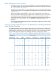
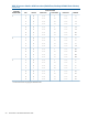
Processor Switch Cable Connections for BladeCluster/NonStop NS16000
Series Solution Topology
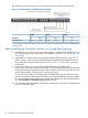
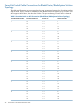
This table shows the port connections between the p-switches (for NS16000 series nodes) and the
ACH in the BladeCluster/NonStop NS16000 series topology. One pair of ACHs is installed for
each BladeCluster and supports up to five NS16000 series nodes. One ACH supports the X fabric;
the other ACH supports the Y fabric. The numbering of the ports on each ACH is identical.
Table 10 Processor Switch to ACH Connections (BladeCluster/NonStop NS16000 Series Solution)
Processor Switch
1
ServerNet
Node Number ACH PortConnects toLC ConnectorConnects to...PIC PortSlot
1<—>4<—>471
9<—>1<—>37
9<—>2<—>27
9<—>3<—>17
17<—>4<—>49
25<—>1<—>39
25<—>2<—>29
25<—>3<—>19
2<—>1<—>472
10<—>1<—>37
10<—>2<—>27
10<—>3<—>17
18<—>1<—>49
26<—>1<—>39
26<—>2<—>29
26<—>3<—>19
Processor Switch Cable Connections for BladeCluster/NonStop NS16000 Series Solution Topology 49