HP NonStop Data Transformation Engine Introduction to the Design Studio Abstract This manual provides information about using the HP NonStop™ Data Transformation Engine (NonStop DTE) Design Studio. Product Version NonStop Data Transformation Engine 6.7.
Document History Part Number Product Version Published 528255-001 NonStop Data Transformation Engine 6.7.1 June 2004 528255-002 NonStop Data Transformation Engine 6.7.
Contents About This Document Related References........................................................................................... 5 Chapter 1 - Design Studio Overview Integration Broker Products ................................................................................ 7 Client Components of the Design Studio ............................................................ 9 Theory of Operation.........................................................................................
Contents Map Settings ............................................................................................. 50 SourceRule Settings .................................................................................... 51 TargetRule Settings .................................................................................... 52 Chapter 5 - Database Interface Designer Overview ...................................................................................................... 53 Database Adapters....
About This Document This document contains information about the Design Studio. This document assumes that the reader knows the Windows environment, has used the Mercator Design Studio, and understands words such as mapping, type trees, and other basic Mercator terminology. Related References Related Reference Description Design Studio Tutorial Performing the basic and advanced aspects of mapping as learned using hands-on tutorials.
About This Document Related References Related Reference Description Command Server Reference Guide Using the Command Server to execute maps on various operating system platforms. Functions and Expressions Reference Guide Creating component rules in the Type Designer and map rules in the Map Designer using expressions, functions, and reserved words.
Chapter 1 - Design Studio Overview This document introduces the concepts, terminology, and capabilities of the Mercator Design Studio. The Design Studio provides the means for developing event-driven application-to-application (A2A) integration, business-to-business (B2B) integration, and consumer-to-business (C2B) application integration. The Design Studio is the design component of the Integration Broker used to model and test your e-business solutions. Use the Design Studio to: ♦ Define your data.
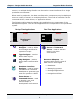
Chapter 1 - Design Studio Overview Integration Broker Products servers, or multiple Design Studios can be used to create interfaces for a single production environment. When used in production, the data transformation components may be deployed across a variety of servers on multiple platforms. The mode of execution can be command-driven, event-driven, or application-driven. The following table shows the design-time applications as components of the development system.
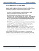
Chapter 1 - Design Studio Overview Integration Broker Products Client Components of the Design Studio The client components of the Design Studio include the Type Designer, Map Designer, Database Interface Designer, and Integration Flow Designer. These designers operate in a Windows environment and provide the graphical interface for managing the integration of applications and business processes. ♦ Integration Flow Designer — The modeling component used to define and manage business processes.
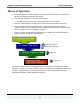
Chapter 1 - Design Studio Overview Theory of Operation Theory of Operation ♦ Use the Integration Flow Designer to design systems of maps to model your data transformation business processes. ♦ Use the Map Designer to develop these maps. ! The Map Designer uses the Command Server to run maps. ♦ Use the Type Designer to define your source and target data structures.
Chapter 2 - Integration Flow Designer The Integration Flow Designer is the graphical process-modeling element of the Design Studio. The Integration Flow Designer is the modeling component for defining and managing business processes. Use the Integration Flow Designer to: ♦ Define interactions among maps and systems of maps. ♦ Specify integration workflow. ♦ Display data flow relationships among system components. ♦ Validate the logical consistency of workflows. ♦ Prepare systems to run.
Chapter 2 - Integration Flow Designer Map Components Map Components The Integration Flow Designer enables you to overwrite settings compiled into maps. Map components of a system provide: ♦ Visual indication of audit log generation. ♦ Identification of the source or target type: message, database, file, or application. ♦ Ability to override map and card settings compiled into a map. ♦ A method of recording your system design with linked documents.
Chapter 2 - Integration Flow Designer Integration Flow Designer Interface The Integration Flow Designer main window also includes a title bar, menu bar, toolbar and status bar. The menu bar and toolbar can be customized to your specific needs. The title bar includes the name of the currently active system and system definition file. The toolbar contains tools that are grouped according to function.
Chapter 2 - Integration Flow Designer Integration Flow Designer Interface The floating toolbox provides access to the tools that are needed to create or modify system diagrams. The toolbox can be moved anywhere on your Windows desktop. Integration Flow Designer Navigator The Integration Flow Designer Navigator presents open system definition (.msd) files and the systems they contain, including map components, cards, log files, doc links, servers, and deploy scripts.
Chapter 2 - Integration Flow Designer Integration Flow Designer Interface The following table lists and briefly describes the icons that appear in the Navigator. Icon Description System definition file (.msd) System or subsystem component (relative to positioning) (blue) Executable map (green) Compiled map (.
Chapter 2 - Integration Flow Designer Integration Flow Designer Interface List View Integration Flow Designer Navigator The List view displays the details of servers and systems. Under Servers, the server definitions are listed alphabetically. Under Systems, the system definition files are listed alphabetically. Each system definition file can be expanded to alphabetically show all the components and deploy scripts it contains.
Chapter 2 - Integration Flow Designer Integration Flow Designer Interface Composition View Integration Flow Designer Navigator The Composition view displays open system definition files and lists all executable systems and their components in a compositional hierarchy. A subsystem appears under the system that contains it; a map component appears under the system or subsystem that contains it. Systems and System Definition Files The Integration Flow Designer graphically organizes maps into systems.
Chapter 2 - Integration Flow Designer Integration Flow Designer Interface The name of the active system definition file and currently selected system appear on the title bar. The system window of the Integration Flow Designer displays the graphical system definition diagram and its map and subsystem components. These components are initially collapsed when created in the system definition diagrams. Map and subsystem components in the system definition diagram may be expanded or collapsed.
Chapter 2 - Integration Flow Designer Integration Flow Designer Interface System Components A map component is an Integration Flow Designer object that represents an executable map and displays its relationship with other components in the same system. Systems can contain one or more map components. To keep the system manageable, you may create smaller systems and then include them as a subsystem of a larger system. Map components and system components are executable units.
Chapter 2 - Integration Flow Designer Integration Flow Designer Interface A map component that references an executable map has a default set of sources and targets defined within the referenced map. Map settings and card settings for sources and targets are defined in the Map Designer, and may be overwritten in the Integration Flow Designer. The sources and targets defined in the map are the interface points of the map component used within a system.
Chapter 3 - Type Designer The Type Designer is the design component used to specify, define, and manage type definitions in the form of type trees. A type tree is a data dictionary that defines how types are classified. The type tree files you create in the Type Designer are data definition files. Each object identified in your data is defined as a type in your type tree.
Chapter 3 - Type Designer Type Designer Interface Type Designer Interface Use the Type Designer interface to define and manage type trees. As illustrated in the diagram below, the interface includes a title bar, menu bar, configurable toolbar, status bar, the type tree window, category windows, group windows, item windows, and the Properties window.
Chapter 3 - Type Designer Type Designer Interface The Type Designer title bar displays both the name of the active type tree and the active window. The toolbar contains tools that are grouped according to function. The status bar displays a descriptive message when the cursor is pointing to a menu item or toolbar tool. The type tree window displays the type tree in a classification hierarchy. Type Tree Window The type tree displays data types in a classification hierarchy in the type tree window.
Chapter 3 - Type Designer Type Trees Type Trees A type tree is a data dictionary because it contains a collection of type definitions. Each type tree is created and managed in the Type Designer. Type trees have a file name extension of .mtt. Each icon in a type tree identifies a data type. The tree has a root type and other types are connected to the tree through branches of the tree.
Chapter 3 - Type Designer Data Objects Two different kinds of fields, Name and Date, may be defined as subtypes of Field. The item type Field describes any field. The Date and Name item types are more specific kinds of fields. The deeper the subtype is in the type tree, the more specific the data characteristics. Data Composition The type tree window does not display the data composition. By looking at a type tree in the type tree window, the composition of the data is not visible.
Chapter 3 - Type Designer Data Objects Item Types An item type represents a simple data object that does not consist of other objects. Blue icons ( ) represent item types. In the following example, the FirstName type does not consist of other data objects; therefore, FirstName is an item type. Group Types A group type represents a complex data object that consists of other objects. Green icons ( , , and ) represent group types. Group types consist of data objects.
Chapter 3 - Type Designer Data Objects For example, FullName is a group type that contains the components that together make up the entire full name: FirstName, MiddleInitial, and LastName. Category Types A category type is used for organizing types in a type tree. Red icons ( ) represent category types. Categories organize types that have common properties. Each category has a set of item properties and a set of group properties. Subtypes of category types inherit these properties.
Chapter 3 - Type Designer Data Objects Components An object that is part of another object is called a component. Components are added and viewed in the group window. In the type tree, double-click a group type to open that type's group window. The green group type icon ( ) and the full name of the group type appear on the title bar of the group window. The group window title bar shows the compositional hierarchy.
Chapter 3 - Type Designer Data Objects An example of how the group window title bar relates to the type tree is shown in the following illustration. The item type Field is a component of the group type Record, which is a subtype of the Root type. The group window may be configured to display the component number and the component range.
Chapter 3 - Type Designer Data Objects Component Ranges The component range specifies the number of consecutive occurrences of that component that may appear at that point in the data stream. The component range appears after the component name in parenthesis and is specified as two numbers separated by a colon (min:max). The group window can be configured to display component ranges in a separate column. A component range of (1:1) specifies a minimum of one occurrence and a maximum of one occurrence.
Chapter 3 - Type Designer Data Objects The type tree for this example contains two group types and multiple item types that represent the data structure. The Field item type is the supertype of the detailed Field item types. The File group type contains the Record group type as a component, with a range of (s), which represents some unknown number of records.
Chapter 3 - Type Designer Data Objects The Record group type components are the item types that represent each kind of field. Each type represents a complete object. The types in the type tree represent each object in the data. The types managed in the Type Designer are used as sources and targets of maps. Maps are created and managed in the Map Designer.
Chapter 4 - Map Designer The Map Designer is the application in the Design Studio that is used to specify data transformation logic in the form of map rules. The Map Designer uses the definition of data objects created in the Type Designer as inputs and outputs and provides the functionality to specify rules for the transformation and routing of data. Maps are analyzed, compiled, and tested using the Map Designer. Each map defines input and output specifications.
Chapter 4 - Map Designer Map Designer Interface Map Designer Interface The Map Designer graphical user interface is used to create and manage maps, run maps, and view map results. The interface includes a title bar, menu bar, configurable toolbar, status bar, Navigator, Rule Bar, and To and From windows.
Chapter 4 - Map Designer Map Designer Interface The map source files and the maps contained in those map source files are shown in the Navigator. Map Designer Navigator The icons and file names that appear in the Navigator graphically represent all of the open map source files and the maps that they contain. Similar to the Integration Flow Designer Navigator, the Map Designer Navigator may be shown or hidden. If shown, the Navigator may be docked or floated.
Chapter 4 - Map Designer Map Designer Interface The maps in Composition view are arranged in a composition hierarchy, while the List view shows the detailed contents of map source files and maps arranged alphabetically. Cars map source file FixedToDelimited executable map FixedRecFile input card DelimitedFile output card RecordMap functional map The List view presents a detailed list of the open map source files, the maps contained in the map source files, and the input and output cards for each map.
Chapter 4 - Map Designer Map Designer Interface Each map source file can be expanded to view all of the maps it contains. Each map can be expanded to view the input and output cards. The input and output card labels may also be expanded to view all of the input and output cards. Navigator Icons In addition to the alphabetical and compositional structure showing the contents of each map source file, information about entries in the Map Designer Navigator is conveyed visually with icons.
Chapter 4 - Map Designer Map Designer Interface From Window The From window represents the input data or the data from which you are mapping. Map cards in the From window of the Map Designer represent source data and are called input cards. The From window contains an input card for each data object from which you are mapping. The input cards in the From window display the composition of the data defined in the Type Designer. The data objects in the cards are in the order they appear in the data stream.
Chapter 4 - Map Designer Map Designer Interface To Window The To window represents the output data to which you are mapping. Map cards in the To window of the Map Designer represent target data and are called output cards. The To window contains an output card for each data object to which you are mapping in the order they appear in the data stream. The cards in the To window have two columns: the Output column and the Rule column. The Output column lists the name of each output data object.
Chapter 4 - Map Designer Map Designer Interface Rule Bar The Rule Bar is one of the main components of the Map Designer graphical user interface. The Rule Bar is used to display and enter map rules for the selected object on the output card in the To window. Similar to the Navigator, the Rule Bar can be docked, floated, shown, or hidden.
Chapter 4 - Map Designer Maps and Map Files Maps and Map Files The Map Designer is used to create and manage maps. Maps are used to retrieve and validate input data, build output data from input data according to the mapping rules you have specified, and then deliver the results to the designated target(s). The tasks involved in creating and managing map files include: ♦ Creating map source files (.mms). ♦ Creating executable and functional maps in the map source file.
Chapter 4 - Map Designer Input and Output Cards ♦ An output card ( ) contains the complete definition of an output for a map. The output definition includes information such as target identification, destination specifics, and the behavior that should occur during processing. Each input of data and each output of data requires content definition settings. The content of each card is specified as a type in a type tree.
Chapter 4 - Map Designer Input and Output Cards The composition of the input and output cards shows the content of the type definitions. Types on the cards are arranged in the order they appear in the data stream. Types on the input and output cards are arranged in a compositional hierarchy that shows the structure, layout, or composition of the data. This composition hierarchy is different from the hierarchy in the type tree, which is a classification hierarchy.
Chapter 4 - Map Designer Input and Output Cards Data Object Names and Card Names The name of the card appears as the top data object of the card. It is possible to name the card the same name as the data object the card represents. Label is the card name Label is also the data object name Note When used in a map rule, the card name appears last in each data object name: FullName Field:CreateLabel.
Chapter 4 - Map Designer Input and Output Cards A unique name for each card in the map provides the ability to distinguish between card objects that may be used in more than one card. For example, if an output card name is CreateLabel, the name for the entire card object is CreateLabel. For example, if two input cards are defined by the same type, these two input cards may exist with the same type, but their card names are different.
Chapter 4 - Map Designer Input and Output Cards Components A component in a data object name is indicated by a colon (:). The colon is the separator between a data object and the group or category type of which it is a component (or the card name in which it is contained). For example, Record is a component of the OrderFile data object. The object name for Record is Record:OrderFile. The name of the Quantity component in the input card shown below is Quantity:Record:OrderFile.
Chapter 4 - Map Designer Map Rules Map Rules A map specifies how to generate a particular output data object, or multiple independent objects, each of a particular type. Each object on an output card has a rule cell in which the corresponding map rule is displayed. Map rules are used to: ♦ Map an input to an output. ♦ Generate desired output, even literal text. ♦ Convert an object in the input data from one value to another value in the output data. ♦ Perform conditional logic.
Chapter 4 - Map Designer Maps Maps Map source files contain two kinds of maps: executable maps and functional maps. Executable Maps An executable map is a map responsible for processing the input data and generating the output data. The sources and targets of an executable map are entire files, database tables, messages, applications, and so on. Think of an executable map as the main map, the top-level map. Executable maps are compiled and run.
Chapter 4 - Map Designer Map Configuration The use of functional maps is very common. Almost every executable map created uses at least one functional map. For example, a functional map may be created to map one message to one row in a database table. Alternatively, you might have a functional map that maps one header and one detail to one item record. Functional maps are used when an output component has a range of more than one. For example, a range of (s) or (1:10).
Chapter 4 - Map Designer Map Configuration Map Settings The map settings specify settings for map execution that are not specific to a particular input or output. These include settings for auditing a map, tracing data content, performance, validation, and map-specific warnings and errors. An executable map has configuration settings to define how to retrieve the input data and route the output data. A map runs as an integral unit of work.
Chapter 4 - Map Designer Map Configuration SourceRule Settings The data object specified in the input card defines what data is retrieved. The SourceRule settings define how the data is retrieved. To define input-specific data retrieval behavior, specify the SourceRule settings for each input card. SourceRule settings specify what data to retrieve, where to get it, how much to get, and what to do when an error occurs. An input card represents an input source.
Chapter 4 - Map Designer Map Configuration TargetRule Settings The data object specified in the output card defines the output data. The TargetRule settings define how and where the output data is routed. To define card-specific output data routing, define the TargetRule settings for each output card. TargetRule settings specify where to send the data, and what to do when an error occurs. An output card represents an output target.
Chapter 5 - Database Interface Designer The Database Interface Designer is used to import metadata about queries, tables, and stored procedures for data stored in relational databases. Use the Database Interface Designer to identify characteristics of those objects to meet mapping and execution requirements such as update keys and database triggers. Use the Database Interface Designer to: ♦ Specify the databases to use for a source or target. ♦ Define query statements.
Chapter 5 - Database Interface Designer Overview Database Adapters The Mercator database adapters provide the connectivity to the RDBMS for retrieving input data and routing output data. Database adapters provide the option of using a driver to connect to the platform of your choice so you can automatically create type trees for database queries and tables. The Windows-based database adapters are installed with the Database Interface Designer as part of the Design Studio.
Chapter 5 - Database Interface Designer Database Interface Designer Interface Database Interface Designer Interface The Database Interface Designer interface is used to create and maintain database/query files and generate type trees. The interface includes a title bar, a menu bar, configurable toolbar, status bar, Navigator, and a main window.
Chapter 5 - Database Interface Designer Database Interface Designer Interface The Database Interface Designer Navigator shows the hierarchical structure and status of the contents of each database/query file. The following table lists and briefly describes the icons that appear in the Database Interface Designer Navigator.
Chapter 5 - Database Interface Designer Database Interface Designer Interface The hierarchical structure shown in the Navigator visually provides information about the contents of each database/query file.
Chapter 5 - Database Interface Designer Database/Query Files Database/Query Files Use the Database Interface Designer when working with database/query files to create database/query files and define the various objects included in a database/query file. A database/query file ( ) contains the definitions for one or more databases, queries, stored procedures, and other specifications that may contribute to the execution of a map.
Chapter 6 - Design and Execution The Design Studio components are primarily used during the design phase of your transformation project. Design-Time Configuration Generating (or creating) the type tree, and modifying type properties, is a design task. Configuring the map settings in the Map Settings dialog box, SourceRule settings in the input card, and TargetRule settings in the output card are tasks performed in the Map Designer during the design phase of your project.
Chapter 6 - Design and Execution Run-Time Configuration Execution Settings Execution settings in the Integration Flow Designer are either Event Server or Command Server settings that are generated for the system. Command Server settings are used when the system is run on a Command Server. Event Server settings are used when the system is run on an Event Server. The settings used are determined by the server upon which the system is run.
Chapter 7 - Customizing Your Environment The Design Studio application toolbars and shortcut keys can be customized to fit your needs. The Options dialog box in each designer application also enables you to set default preferences. Customizing Toolbars You can customize the standard toolbar or create your own. You can also delete and rearrange tools within a toolbar. ♦ Delete a tool from a toolbar. Press the Alt key and drag the tool off the toolbar. ♦ Rearrange tools on a toolbar.
Chapter 7 - Customizing Your Environment Customizing Toolbars ♦ Customize the appearance of the tools. You can select options for showing tool tips, viewing the tools as flat (Cool Look check box enabled) or raised, and specifying small or large tools on the toolbar (Large Buttons check box enabled). To reset a toolbar to its default configuration 1 From the View menu, choose Toolbar(s). 2 From the Toolbars tab, select the toolbar you want to reset and click Reset.
Chapter 7 - Customizing Your Environment Customizing Toolbars To create a new toolbar 1 From the View menu, choose Toolbar(s). 2 On the Customize dialog box, click New. 3 Enter a name for the toolbar (for example, Editing) and click OK. 4 Select the new toolbar in the Customize dialog box. The new toolbar appears on your screen. 5 Select the Commands tab. 6 Drag each tool that you want into the new toolbar. 7 Click OK to save the toolbar when you are finished.
Chapter 7 - Customizing Your Environment Shortcut Keys Shortcut Keys You can assign your own shortcut actions to keys. To assign shortcut keys 1 From the Tools menu, choose Short Cuts. The Shortcut Keys dialog box appears. 2 In the Select a macro list in the Shortcut Keys dialog box, select a command to which you want to assign a shortcut key. 3 Click Create Shortcut.
Chapter 7 - Customizing Your Environment 4 Shortcut Keys Enter the keystroke(s) you want to assign. For example, to use the keystroke(s) Ctrl+Shift+J, press and hold the Ctrl key and the Shift key, then press J. A message displays that indicates whether the shortcut is currently assigned. 5 After you finish assigning shortcuts, click OK. To view the shortcut assignment for a command, select the command. A description of the command and the assigned shortcut keys are displayed.
Chapter 8 - Design Studio Reference This chapter contains reference material that applies to all components of the Design Studio. Quotation Marks Although there are platform-specific limitations regarding the usage of double and single quotation marks, when adding a text string into any map rule, component rule, or command line, use the following characters for quotation marks.
Chapter 8 - Design Studio Reference Reserved Words and Symbols Reserved Word or Symbol Intended Use :.: Shorthand representation of a unique component or partition path. For example, A:.:B refers to the unique path from the type A to the type B. <> Separates a partition from its partitioned type. , Used to separate arguments of functions and maps. "" Used to enclose literal text strings. () Used for a component range, to enclose function or map arguments, and to block sub-expressions in a rule.
Chapter 8 - Design Studio Reference Non-printable Hex and Decimal Values Reserved Word or Symbol Intended Use LAST Special index value that refers to the previous data object of a particular series. NONE Stands for the null value or non-existence of data content. Can be used in a component rule to test the presence of data. Can be used in a map rule to generate no occurrences of an output. Separates type names. TRUE Represents the logical true.
Chapter 8 - Design Studio Reference Non-printable Hex and Decimal Values Character Hex value Decimal value Abbreviation NULL 00 0 StartOfHeading 01 1 StartofTeXt 02 2 EndofTeXt 03 3 EndOfTrans.
Chapter 8 - Design Studio Reference Non-printable Hex and Decimal Values Character Hex value Decimal value Abbreviation ESCape 1B 27 FileSeparator 1C 28 GroupSeparator 1D 29 RecordSep.
Chapter 9 - Additional Resources For quick and easy access to all the information, the Mercator Online Library contains thousands of pages of information about Mercator products in Adobe Acrobat PDF format. The Mercator Online Library is available on the Customer Zone of the www.mercator.com Web site and on a CD-ROM. Another source for learning about Mercator products is the \Examples folder that is installed with the Design Studio product.
Chapter 9 - Additional Resources Examples Examples Example maps, type trees, systems, and other data transformation business objects are also available on the Customer Zone of the www.mercator.com Web site and the www.myMercator.com Web site.
Index customize toolbars, 61 $ $ D reserved symbol, 66 data composition, 25 data object definition of, 25 Database Interface Designer interface, 55 ( () reserved symbol, 67 E : : executable maps definition, 48 execution settings definition of, 19 reserved symbol, 66 @ @ F reserved symbol, 67 FALSE reserved word, 67 From window definition of, 38 Functional Map Wizard, 49 functional maps definition, 48 [ [] reserved symbol, 67 { {} reserved symbol, 67 G group type definition of, 26 < <> rese
Index Examples list of, 66 Rule Bar, 40 L LAST reserved word, 68 S subsystems overview of, 18 subtype definition of, 24 supertype definition of, 24 system definition files definition of, 17 systems definition of, 17 overview of, 18 M map component definition of, 19 Map Designer, 33 interface, 34 map rule definition, 47 map source file definition of, 41 maps definition, 48 T N theory of operation Design Studio, 10 To window definition of, 39 toolbars customize, 61 TRUE reserved word, 68 type definitio